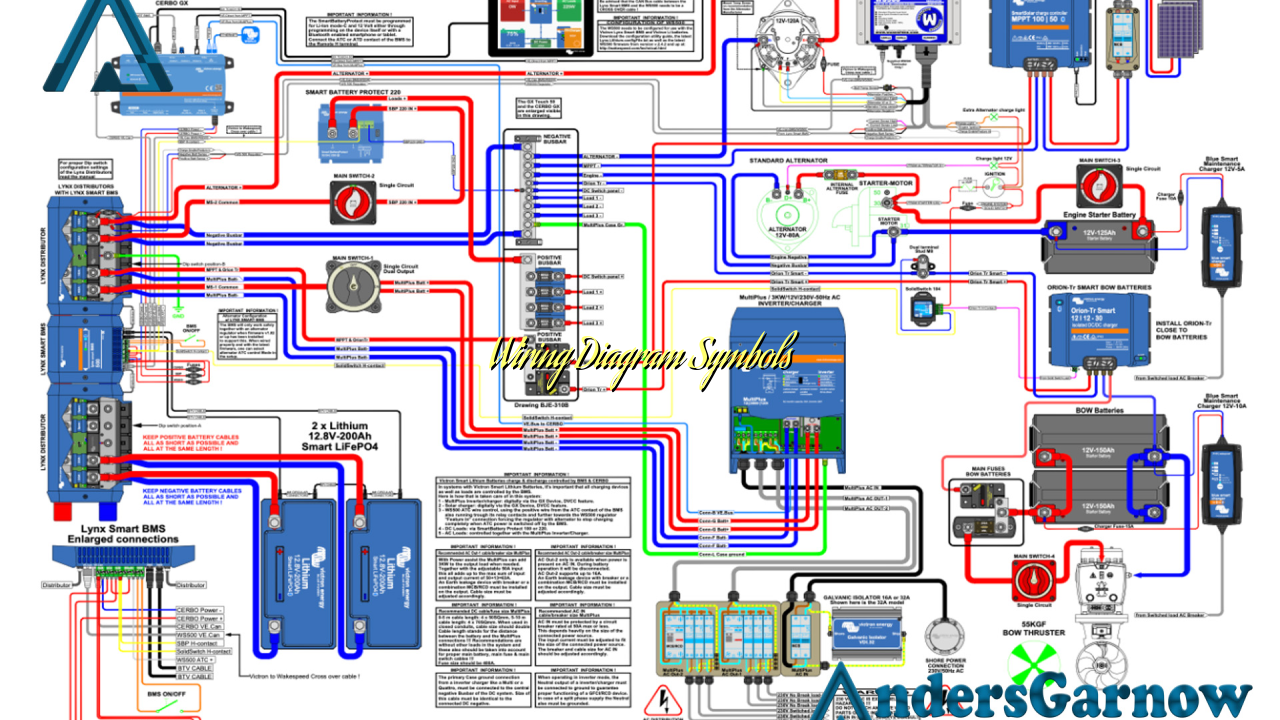
Hello readers! In this article, we will delve into the world of wiring diagram symbols. Wiring diagrams are essential tools used by electricians and technicians to understand and troubleshoot electrical circuits. These diagrams use symbols to represent various components and connections, making it easier to interpret complex electrical systems. Let’s explore this topic further through ten subheadings.
1. Importance of Wiring Diagram Symbols
Wiring diagram symbols play a crucial role in electrical engineering as they provide a standardized language for representing electrical components and connections. They allow professionals to understand and communicate complex circuit designs effectively. Without these symbols, it would be challenging to interpret and document electrical systems accurately.
Advantages:
- Facilitates clear communication among professionals.
- Ensures consistency in circuit documentation.
- Simplifies troubleshooting and maintenance.
Disadvantages:
- Requires training to understand the symbols correctly.
- May not include symbols for rare or specialized components.
- Can be overwhelming for beginners due to the sheer number of symbols.
2. Commonly Used Wiring Diagram Symbols
Here are some of the most commonly used wiring diagram symbols:
| Symbol | Description |
|---|---|
 Source: None Source: None |
Represents a resistor, a passive two-terminal component that restricts the flow of electric current. |
 Source: None Source: None |
Indicates a capacitor, an electronic component that stores electrical energy in an electric field. |
 Source: None Source: None |
Represents an inductor, a passive two-terminal component that stores energy in a magnetic field. |
 Source: None Source: None |
Denotes a battery, a device that converts chemical energy into electrical energy. |
 Source: None Source: None |
Indicates a switch, a device used to interrupt or divert the flow of electric current. |
 Source: None Source: None |
Represents a lamp or light bulb, a device that produces light when an electric current passes through it. |
These are just a few examples, and there are numerous other symbols used to represent various components like transformers, diodes, transistors, and more.
3. Alternatives to Wiring Diagram Symbols
While wiring diagram symbols are the standard in the electrical industry, there are alternative methods to represent electrical circuits. One such method is the use of color-coded wires. Different colors indicate different functions or types of wires, simplifying the understanding of circuit connections. However, color-coded wiring diagrams may not be as universally understood as symbols, especially in international collaborations or when dealing with complex systems.
4. Frequently Asked Questions (FAQ)
Q: Can I create my own wiring diagram symbols?
A: Yes, you can create your own symbols if you encounter components or connections not represented by standard symbols. However, it is crucial to document and explain these symbols to ensure clear communication with others.
Q: Where can I find a comprehensive list of wiring diagram symbols?
A: There are various resources available online and in electrical engineering textbooks that provide comprehensive lists of wiring diagram symbols. These resources often include explanations and illustrations to help you understand and interpret the symbols accurately.
Q: Are wiring diagram symbols the same globally?
A: While many wiring diagram symbols are standardized, some variations may exist regionally or between different industries. It is essential to confirm the symbols’ meanings and conventions specific to your location or field of work.
Q: Can I use wiring diagram symbols for other purposes?
A: Wiring diagram symbols are primarily used for electrical circuits. However, some symbols may have similar representations in other fields, such as electronics or HVAC systems. It is crucial to consider the context and ensure the symbols align with the intended purpose.
Q: How can I learn to interpret wiring diagram symbols?
A: Learning to interpret wiring diagram symbols requires practice and familiarity with electrical circuits. Electrical engineering courses, textbooks, and online resources can provide valuable guidance and exercises to improve your understanding.
Q: Are there software tools available for creating wiring diagrams?
A: Yes, there are various software tools specifically designed for creating wiring diagrams. These tools often include libraries of standard symbols and features to facilitate the creation and editing of diagrams.
Q: Can I use wiring diagrams for home electrical projects?
A: Wiring diagrams are primarily used in professional settings. For home electrical projects, it is recommended to consult a qualified electrician or refer to specific wiring diagrams provided by electrical code regulations or reputable sources.
Q: Can I modify existing wiring diagrams to suit my needs?
A: Modifying existing wiring diagrams can be done, but it is crucial to ensure the changes accurately represent the intended modifications. Care must be taken to avoid misinterpreting or miscommunicating the circuit design.
In conclusion, wiring diagram symbols are vital tools for understanding and documenting electrical circuits. They provide a standardized language that simplifies communication between professionals in the field of electrical engineering. While they have their advantages and disadvantages, symbols remain the most widely used method for representing electrical components and connections. By familiarizing yourself with these symbols and their meanings, you can enhance your understanding of electrical circuits and effectively troubleshoot complex systems.

