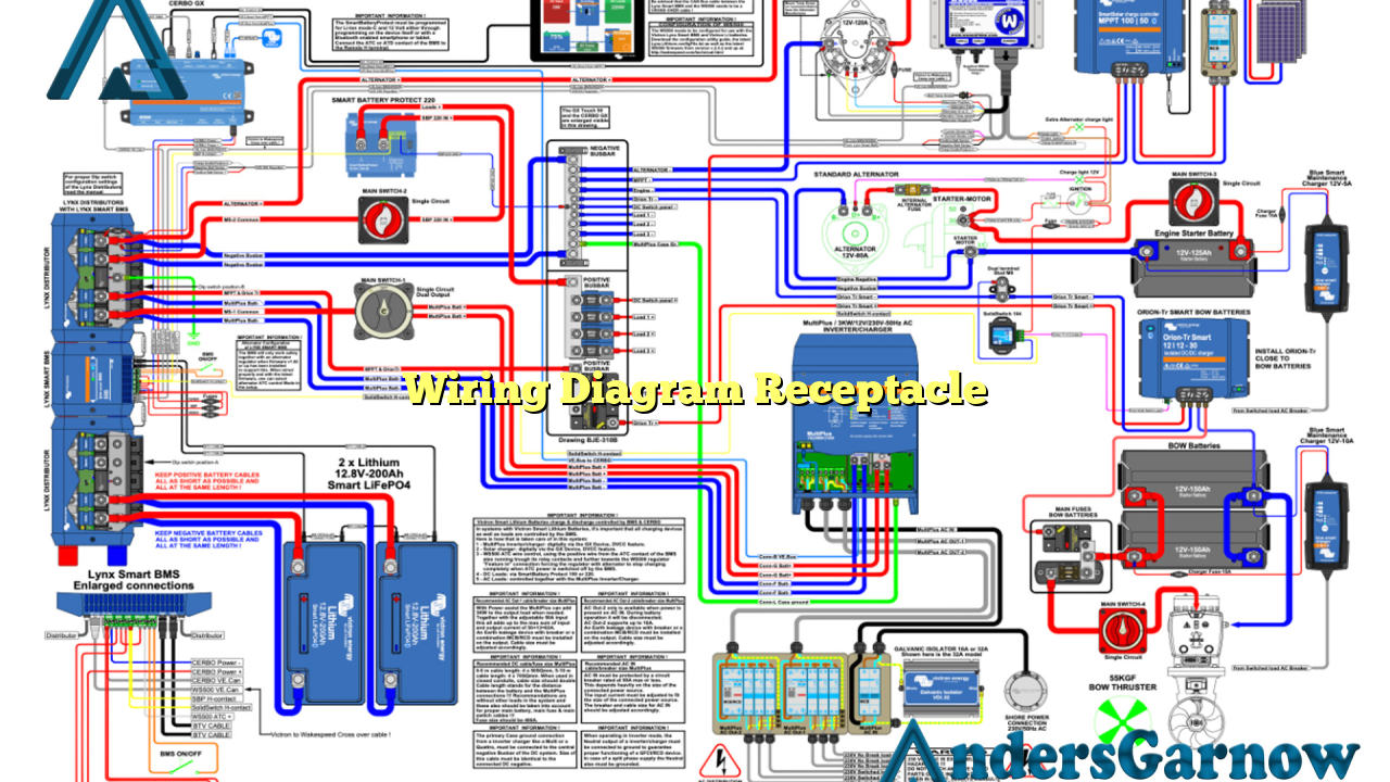
Hello there! In this article, we will delve into the world of wiring diagram receptacles. Whether you are an electrician, a DIY enthusiast, or simply curious about electrical connections, understanding wiring diagrams is essential. So, let’s explore the ins and outs of wiring diagram receptacles.
1. What is a Wiring Diagram Receptacle?
A wiring diagram receptacle is a visual representation of the electrical connections and layout of a receptacle. It provides a detailed illustration of how the various wires and components are interconnected, ensuring safe and efficient electrical operation.
Advantages:
– Provides a clear understanding of the electrical connections
– Helps in troubleshooting and identifying potential issues
– Ensures proper wiring installation
Disadvantages:
– Requires basic knowledge of electrical symbols and conventions
– May vary depending on the specific receptacle type
2. Understanding the Symbols
Wiring diagram receptacles utilize various symbols to represent different electrical components. Some common symbols include:
| Symbol | Description |
|---|---|
| ⚫ | Electrical junction point |
| ⚬ | Wire connection |
| △ | Ground connection |
| ↔ | Two-way switch |
| ⇑ | Power supply |
3. Types of Receptacles
There are several types of receptacles commonly used in residential and commercial settings. Some of these include:
– Standard Receptacles: These are the most common type of receptacles found in homes and offices. They provide power for various devices and appliances.
– GFCI Receptacles: Ground Fault Circuit Interrupter (GFCI) receptacles are designed to protect against electrical shocks. They are commonly installed in bathrooms, kitchens, and outdoor areas.
– AFCI Receptacles: Arc Fault Circuit Interrupter (AFCI) receptacles are designed to detect potentially dangerous electrical arcs and prevent fires. They are typically used in bedrooms and living areas.
– USB Receptacles: These receptacles feature built-in USB ports, allowing you to charge your devices directly without the need for adapters.
4. Wiring Diagram Receptacle Installation
Proper installation of a receptacle is crucial for safety and functionality. Here’s a step-by-step guide:
Step 1: Turn off the power supply to the circuit you’ll be working on.
Step 2: Gather the necessary tools and materials, including a receptacle, wires, wire strippers, and screwdrivers.
Step 3: Follow the wiring diagram receptacle specific to your type of receptacle and make the appropriate connections.
Step 4: Double-check all connections and ensure they are secure.
Step 5: Carefully insert the receptacle into the electrical box and secure it with screws.
Step 6: Restore power to the circuit and test the receptacle to ensure it is functioning correctly.
5. Common Wiring Diagram Receptacle Issues
While wiring diagram receptacles aim to provide accurate guidance, issues can still arise. Here are some common problems and their possible solutions:
– Loose connections: Ensure all wires are firmly connected to their respective terminals.
– Faulty wiring: Inspect the wiring for any signs of damage or wear and replace if necessary.
– Tripped circuit breaker: Check the circuit breaker panel and reset any tripped breakers.
– Overloaded circuit: If the receptacle is being overloaded, redistribute the load or consider installing additional circuits.
Alternative to Wiring Diagram Receptacle
If you find wiring diagram receptacles too complex or time-consuming, an alternative is to hire a licensed electrician. They have the expertise and knowledge to handle your electrical needs professionally and ensure compliance with electrical codes and regulations.
Conclusion
In conclusion, understanding wiring diagram receptacles is crucial for anyone working with electrical connections. It provides a clear and detailed overview of the wiring layout, ensuring safe and efficient electrical operation. By following the provided guidelines and symbols, you can confidently install and troubleshoot receptacles. Remember, safety should always be the top priority when working with electricity.

