Hello, readers! Today, we will delve into the topic of the wiring diagram of a photocell. In this article, we will explore the various aspects of a photocell’s wiring diagram, its advantages, disadvantages, and provide alternative options. So, let’s get started!
1. Understanding the Basics
Before we dive into the wiring diagram, let’s understand what a photocell is. A photocell, also known as a photoresistor or light-dependent resistor (LDR), is a sensor that detects light levels. It is often used in outdoor lighting systems to automatically switch the lights on and off based on the ambient light conditions. Now, let’s move on to the wiring diagram.
2. Wiring Diagram Overview
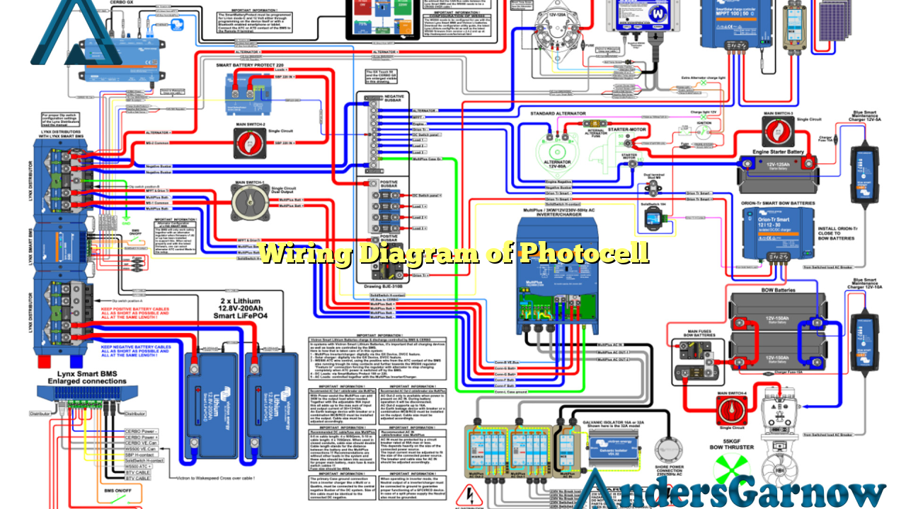
A typical wiring diagram of a photocell consists of a few key components. It includes the photocell itself, a power source, a switch or relay, and the lighting fixture. The power source supplies electricity to the system, while the switch or relay controls the circuit based on the photocell’s readings. The lighting fixture is connected to the circuit and is activated or deactivated depending on the light levels detected by the photocell.
3. Wiring Diagram Components
Now, let’s take a closer look at each component of the wiring diagram:
- Photocell: This is the main sensor that measures the light intensity and sends signals to the switch or relay.
- Power Source: It provides the electrical energy required to power the entire system.
- Switch or Relay: This component controls the flow of electricity based on the photocell’s readings.
- Lighting Fixture: The actual light source that is connected to the circuit and turns on or off based on the switch or relay’s state.
4. Wiring Diagram Connection
To establish the wiring diagram, the components are interconnected as follows:
| Component | Connection |
|---|---|
| Photocell | Connect the two wires of the photocell in series with the power source and the switch or relay. |
| Power Source | Connect one wire of the power source to the common terminal of the switch or relay and the other wire to the lighting fixture. |
| Switch or Relay | Connect the normally open (NO) terminal of the switch or relay to the lighting fixture. |
| Lighting Fixture | Connect the wire from the power source and the wire from the switch or relay to the lighting fixture. |
5. Advantages of Photocell Wiring Diagram
The wiring diagram of a photocell offers several advantages:
- Energy Efficiency: The photocell ensures that the lights are only active when necessary, leading to energy savings.
- Convenience: The automated control of lighting based on ambient light conditions eliminates the need for manual switching.
- Cost-Effective: By reducing unnecessary lighting, the lifespan of the lighting fixtures can be extended, resulting in cost savings.
- Safety: The photocell allows for consistent lighting levels, enhancing safety in outdoor areas.
6. Disadvantages of Photocell Wiring Diagram
However, it is important to consider the potential drawbacks of using a photocell wiring diagram:
- Dependency on Light: The system relies heavily on the availability of natural light, which may not be suitable for all applications.
- Environmental Factors: Extreme weather conditions or obstructions may affect the accuracy of the photocell’s readings.
- Installation Complexity: Proper installation of the wiring diagram requires technical expertise and knowledge.
7. Alternative Wiring Options
In addition to the traditional wiring diagram, there are alternative options available for incorporating photocells:
- Wireless Technology: Some advanced photocell systems utilize wireless communication to control the lighting, eliminating the need for extensive wiring.
- Integrated Sensors: Certain lighting fixtures come with built-in photocells, simplifying the installation process.
8. Frequently Asked Questions (FAQ)
Q: Can a photocell be used indoors?
A: Yes, photocells can be used indoors, but they are primarily designed for outdoor applications where the ambient light conditions vary.
Q: Can I manually override the photocell system?
A: Depending on the specific setup, some photocell systems offer manual override options, allowing users to control the lighting manually when needed.
Conclusion
In conclusion, the wiring diagram of a photocell plays a crucial role in automatically controlling lighting based on ambient light levels. It offers energy efficiency, convenience, cost-effectiveness, and improved safety. However, it also has limitations related to light dependency, environmental factors, and installation complexity. Considering alternative options such as wireless technology and integrated sensors can provide additional flexibility. If properly implemented, a photocell system can greatly enhance the efficiency and functionality of outdoor lighting systems.

