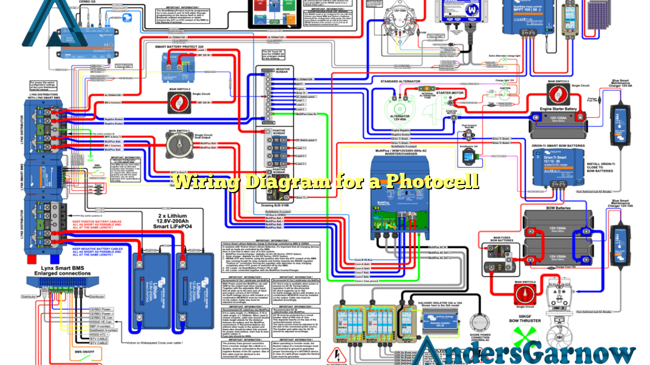
Hello readers! In this article, we will delve into the world of wiring diagrams for a photocell. A photocell, also known as a photoresistor or light-dependent resistor (LDR), is an essential component used in various electronic circuits. It is primarily employed to detect and respond to changes in light intensity. Understanding how to wire a photocell correctly is crucial for ensuring its optimal functionality. Let’s explore the wiring diagram for a photocell in detail.
Subheading 1: What is a Photocell?
Before we dive into the wiring diagram, let’s briefly discuss what a photocell is. A photocell is a sensor that changes its resistance depending on the amount of light it is exposed to. It consists of a semiconductor material that exhibits photoconductivity. When light falls on the semiconductor, electrons are excited, resulting in a decrease in resistance. This change in resistance can be utilized to trigger or control various electronic devices.
Subheading 2: Components Required
Now that we understand the basics, let’s move on to the components required for wiring a photocell. To wire a photocell, you will need the following:
| Component | Description |
|---|---|
| Photocell | The light-sensitive component that detects changes in light intensity. |
| Power Source | A power supply to provide the necessary voltage for the circuit. |
| Load | The device or circuit that you want to control based on light intensity. |
| Resistor | A resistor to limit the current flowing through the circuit. |
| Connecting Wires | Wires to establish the connections between the components. |
Subheading 3: Wiring Diagram
Now, let’s move on to the wiring diagram itself. Please refer to the table below for a detailed explanation of each connection:
| Connection | Description |
|---|---|
| Connect one end of the photocell to the positive terminal of the power source. | This connection allows the photocell to receive power. |
| Connect the other end of the photocell to one end of the load. | This connection allows the current to flow through the load. |
| Connect the other end of the load to the negative terminal of the power source. | This connection completes the circuit and allows the load to function based on light intensity. |
| Connect a resistor in series with the load. | This connection helps in limiting the current flowing through the circuit and protects the components. |
Subheading 4: Advantages of Using a Photocell
Using a photocell in electronic circuits offers several advantages:
- Automatic Control: A photocell enables automatic control of devices based on ambient light levels, eliminating the need for manual intervention.
- Energy Efficiency: By utilizing a photocell, energy consumption can be optimized by controlling lighting or other devices based on natural light availability.
- Cost-Effective: Photocells are relatively inexpensive, making them a cost-effective solution for light sensing applications.
- Reliability: Photocells are known for their long lifespan and reliability, ensuring consistent performance over extended periods.
Subheading 5: Limitations of Using a Photocell
While photocells offer numerous benefits, they also have some limitations:
- Inaccuracy: Photocells may not provide precise light readings due to factors like ambient light interference and the response time of the sensor.
- Nonlinear Response: The resistance of a photocell does not change linearly with light intensity, making it challenging to obtain precise control over certain applications.
- Environmental Factors: External factors such as temperature and humidity can affect the performance and reliability of photocells.
Subheading 6: Alternative Wiring Diagram
An alternative wiring diagram for a photocell involves using the photocell in a voltage divider circuit. In this setup, the photocell is connected in series with a resistor, and the junction between them is connected to the input of an analog-to-digital converter (ADC) or microcontroller. The voltage across the photocell can be measured and used to determine the light intensity.
FAQs (Frequently Asked Questions)
1. Can I use a photocell to control outdoor lighting?
Yes, photocells are widely used in outdoor lighting systems to automatically turn on/off the lights based on the ambient light levels.
2. Can I connect multiple loads to a single photocell?
Yes, it is possible to connect multiple loads to a single photocell. However, the total current drawn by the loads should be within the photocell’s specified limits.
3. How do I choose the right resistor for my photocell circuit?
The value of the resistor depends on the specific requirements of your circuit. You can refer to the datasheet of the photocell to determine the recommended resistor value for optimal performance.
Conclusion
In conclusion, understanding the wiring diagram for a photocell is crucial for its correct installation and usage. By following the proper connections and considering the advantages and limitations of using a photocell, you can effectively incorporate this light-sensing component into your electronic projects. Remember to choose the appropriate components and ensure the accuracy and reliability of your circuit for optimal performance.

