Hello and welcome to our article on wiring diagrams for a contactor. In this article, we will provide you with detailed information on how to properly wire a contactor, its advantages and disadvantages, as well as alternative wiring options. Whether you are an electrician or a DIY enthusiast, understanding the correct wiring diagram for a contactor is essential for a safe and efficient electrical system. So, let’s dive right in!
Subheading 1: What is a Contactor?
Before we delve into the wiring diagram, let’s first understand what a contactor is. A contactor is an electrical switch used for controlling an electrical power circuit. It is typically used in applications where high-power loads need to be controlled remotely. Contactors are often found in HVAC systems, industrial machinery, and motor control circuits.
Subheading 2: Advantages of Using a Contactor
There are several advantages to using a contactor in electrical systems:
| Advantages | Explanation |
|---|---|
| 1. Increased Safety | Contactors provide a safe way to control high-power loads, reducing the risk of electrical shock or fire hazards. |
| 2. Remote Control | Contactor coils can be controlled remotely, allowing for convenient operation of electrical circuits. |
| 3. Reduced Voltage Drop | By using contactors, voltage drops across long cable runs can be minimized, ensuring efficient power delivery. |
| 4. Longevity | Contactors are designed to handle high-current loads and have a longer lifespan compared to other switching devices. |
Subheading 3: Disadvantages of Using a Contactor
While contactors offer many benefits, there are a few disadvantages to be aware of:
- 1. Size: Contactors are generally larger in size compared to other switching devices, requiring adequate space for installation.
- 2. Cost: Contactors can be more expensive than traditional switches, especially for larger power ratings.
- 3. Noise: Contactors can produce audible noise when switching, which may be a concern in certain applications.
Subheading 4: Wiring Diagram for a Contactor
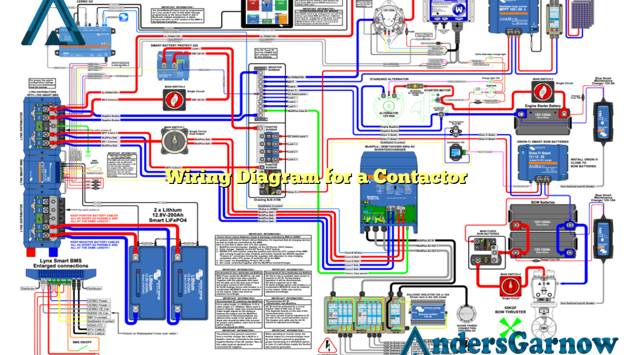
Now, let’s take a look at a typical wiring diagram for a contactor:
| Contact | Coil | Power Supply | Load |
|---|---|---|---|
| L1 | A1 | L1 | Connected to Load |
| L2 | A2 | L2 | Connected to Load |
| L3 | A3 | L3 | Connected to Load |
To wire a contactor, connect the power supply lines (L1, L2, L3) to the corresponding contact terminals (A1, A2, A3), and connect the load to the load terminals. Ensure proper insulation and secure connections for safe and reliable operation.
Subheading 5: Alternative Wiring Options
While the above wiring diagram is a common configuration, there are alternative options available depending on your specific application. Some alternatives include:
- 1. Reversing Contactor Wiring: Used in applications where the motor needs to rotate in both directions.
- 2. Two-Wire Control: Used for simple on/off control of a motor or load.
- 3. Three-Wire Control: Provides an additional control circuit for enhanced functionality.
Consult the manufacturer’s documentation or a qualified electrician for the appropriate wiring diagram based on your requirements.
FAQ (Frequently Asked Questions)
Q: Can I use a contactor to control a lighting circuit?
A: Yes, contactors can be used to control lighting circuits, especially in commercial or industrial settings where high-power lighting is required.
Q: Is it necessary to use a contactor for low-power loads?
A: While contactors are typically used for high-power loads, they can also be used for low-power loads if remote control or other features are desired.
Q: How do I select the right contactor for my application?
A: Consider factors such as the load current, voltage, and type of load when selecting a contactor. Consult manufacturer specifications or seek professional advice for proper selection.
Conclusion
In conclusion, understanding the wiring diagram for a contactor is crucial for safe and efficient electrical systems. Contactors offer numerous advantages, including increased safety and remote control capabilities. However, they also have some drawbacks, such as their size and cost. By following the correct wiring diagram and considering alternative options, you can ensure the reliable operation of your electrical circuits. If in doubt, always consult a professional electrician for assistance.

