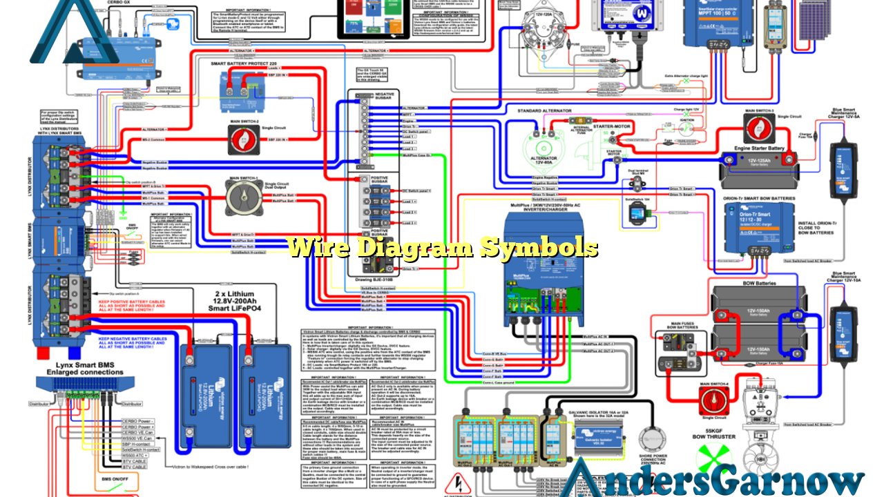
Hello! Welcome to our comprehensive guide on wire diagram symbols. In this article, we will explore the various symbols used in wire diagrams, their meanings, and their importance in electrical engineering. So, let’s dive in and unravel the world of wire diagram symbols!
1. The Importance of Wire Diagram Symbols
Wire diagram symbols are essential tools that help professionals in the electrical engineering field to understand and communicate complex electrical systems and circuits. These symbols serve as a common language, allowing engineers to convey information accurately and efficiently.
By using standardized symbols, wire diagrams become universal and can be easily interpreted by technicians, electricians, and engineers across different industries and countries. This uniformity ensures consistent understanding and minimizes errors during system design, installation, and troubleshooting processes.
Advantages of Wire Diagram Symbols:
| Advantages | Explanation |
|---|---|
| Clear Communication | Wire diagram symbols provide a concise and clear way to represent complex electrical systems, enabling effective communication between professionals. |
| Efficient Troubleshooting | With standardized symbols, technicians can quickly identify faulty components and troubleshoot electrical systems, saving time and resources. |
| Easy Collaboration | Wire diagrams with symbols allow engineers from different disciplines to collaborate seamlessly, ensuring the successful implementation of electrical projects. |
| Accurate Documentation | By using symbols, engineers can create detailed and precise documentation of electrical systems, ensuring easy replication and maintenance in the future. |
Disadvantages of Wire Diagram Symbols:
While wire diagram symbols offer numerous benefits, there are also a few limitations to consider:
- Learning Curve: Understanding and memorizing the different symbols can be time-consuming, especially for beginners in the field.
- Complexity: Some electrical systems may require a large number of symbols, leading to intricate diagrams that can be challenging to interpret.
- Subjectivity: In rare cases, interpretations of symbols may vary slightly between individuals or organizations, leading to minor discrepancies.
2. Commonly Used Wire Diagram Symbols
In this section, we will explore some of the most commonly used wire diagram symbols and their meanings:
Symbol 1: Resistor (R)
The resistor symbol represents a passive two-terminal electrical component that resists the flow of electric current. It is commonly used to control the amount of current or voltage in a circuit.
Symbol 2: Capacitor (C)
The capacitor symbol represents a device that stores and releases electrical energy. It consists of two conductive plates separated by an insulating material.
Symbol 3: Inductor (L)
The inductor symbol represents a passive two-terminal electrical component that stores energy in a magnetic field when current flows through it. It resists changes in current.
Symbol 4: Diode (D)
The diode symbol represents a device that allows current to flow in one direction while blocking it in the opposite direction. It is commonly used to convert alternating current (AC) to direct current (DC).
Symbol 5: Transformer (T)
The transformer symbol represents a device that transfers electrical energy between two or more circuits through electromagnetic induction. It is commonly used to step up or step down voltage levels.
Symbol 6: Switch (S)
The switch symbol represents a device that can open or close a circuit, controlling the flow of current. It is used to turn electrical devices on or off.
Symbol 7: Ground (Earth) Connection
The ground symbol represents a connection to the Earth, providing a reference point for electrical circuits. It ensures safety and helps reduce electrical noise.
Symbol 8: Battery
The battery symbol represents a device that stores and provides electrical energy. It is commonly used as a power source in electrical circuits.
Symbol 9: Fuse
The fuse symbol represents a safety device designed to protect electrical circuits from excessive current. It melts or breaks the circuit when the current exceeds a predetermined limit.
Symbol 10: Light Emitting Diode (LED)
The LED symbol represents a semiconductor device that emits light when an electric current passes through it. It is commonly used in electronic displays and indicators.
Alternative Symbols for Wire Diagrams
While wire diagram symbols have become standardized, there are alternative symbols used in specific industries or regions. These variations may arise due to historical reasons, cultural preferences, or specific industry practices.
For example, in the automotive industry, different symbols may be used to represent electrical components specific to vehicles. Similarly, certain countries may have slight variations in symbol design to accommodate their native language or industry standards.
It is crucial to consider these alternative symbols when working on projects involving specific industries or regions to ensure accurate communication and interpretation.
Frequently Asked Questions (FAQ)
1. What is the best way to learn wire diagram symbols?
Ans: The best way to learn wire diagram symbols is through formal education or training programs in electrical engineering. Online resources, textbooks, and practical hands-on experience can also be valuable.
2. Are wire diagram symbols the same globally?
Ans: While wire diagram symbols have a general standardization, minor variations may exist between regions or industries. It is essential to be aware of these differences to ensure accurate interpretation.
3. Can I create my own wire diagram symbols?
Ans: Yes, in specific cases, organizations or individuals may create customized symbols to accommodate unique requirements. However, it is crucial to document and communicate these symbols effectively within the relevant community.
Conclusion
In conclusion, wire diagram symbols play a vital role in electrical engineering, enabling professionals to communicate and understand complex electrical systems efficiently. With standardized symbols, engineers can ensure clear communication, efficient troubleshooting, easy collaboration, and accurate documentation. While wire diagram symbols offer numerous advantages, they also have a learning curve and can be complex. It is important to be aware of alternative symbols used in specific industries or regions. By mastering wire diagram symbols, professionals can navigate the world of electrical engineering with confidence and precision.

