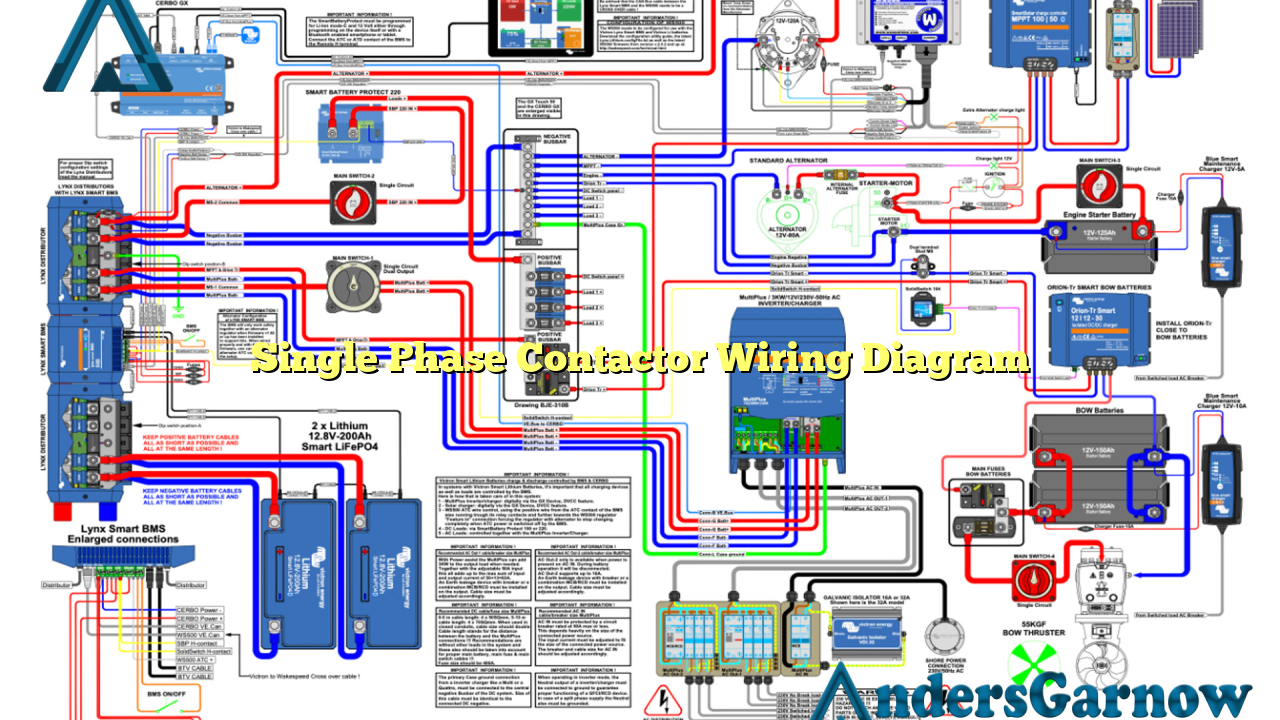
Hello readers, in this article we will discuss the wiring diagram of a single phase contactor. A contactor is an electrical device used for switching an electrical power circuit. It is commonly used in various applications such as motor control, lighting control, and heating systems. Understanding the wiring diagram of a single phase contactor is essential for proper installation and operation. So, let’s dive into the details!
1. What is a Single Phase Contactor?
A single phase contactor is an electromagnetic switch that is used to control the flow of electrical power in a single phase system. It consists of a coil, contacts, and an enclosure. The coil generates a magnetic field when supplied with electrical current, which attracts the contacts and closes the circuit. This allows the electrical power to flow through the connected load.
2. Wiring Diagram Components
A single phase contactor wiring diagram consists of several components:
| Component | Description |
|---|---|
| Contactors | Electromagnetic switches used to control the flow of electrical power. |
| Coil | A coil of wire that generates a magnetic field when supplied with electrical current. |
| Contacts | Electrical connections that open or close the circuit based on the magnetic field generated by the coil. |
| Enclosure | A protective housing that contains the contactor and prevents accidental contact with live parts. |
3. Wiring Diagram Connections
The wiring diagram of a single phase contactor includes various connections:
- Power Supply: The contactor is connected to the power supply, which provides electrical current for the coil.
- Load: The contactor is connected to the load, which is the device or equipment that requires electrical power.
- Control Circuit: The contactor is controlled by a control circuit, which can be a switch, thermostat, or any other control device.
- Overload Relay: In some cases, an overload relay is connected in series with the contactor to protect the motor or load from excessive current.
4. Advantages of Single Phase Contactor
The use of a single phase contactor offers several advantages:
- Efficient Power Control: Contactors provide efficient control of electrical power, allowing for easy switching of the load.
- Compact Size: Single phase contactors are compact in size, making them suitable for applications with limited space.
- Reliable Operation: Contactors are designed for reliable operation, ensuring the uninterrupted flow of electrical power.
- Easy Installation: The wiring diagram of a single phase contactor is relatively simple, making it easy to install and connect.
5. Disadvantages of Single Phase Contactor
Despite their advantages, single phase contactors have some limitations:
- Limited Power Capacity: Single phase contactors are suitable for low to moderate power applications. For high power requirements, three phase contactors are more appropriate.
- Noisy Operation: Contactors can produce noise during switching due to the magnetic field generated by the coil.
- Higher Cost: Compared to other types of switches, contactors can be more expensive.
6. Alternative Wiring Diagram
Another alternative for single phase contactor wiring is using a motor starter. A motor starter consists of a contactor, overload relay, and a start-stop push button. It provides additional protection and control features for the motor. The wiring diagram for a motor starter is more complex but offers enhanced functionality.
7. Frequently Asked Questions
Q: Can a single phase contactor be used for three phase applications?
A: No, a single phase contactor is designed for single phase systems and is not suitable for three phase applications. For three phase systems, three phase contactors should be used.
Q: How to wire a single phase contactor for a motor?
A: To wire a single phase contactor for a motor, connect the power supply to the contactor coil terminals, connect the motor to the contactor load terminals, and connect the control circuit to the contactor control terminals.
Q: What is the purpose of an overload relay in a single phase contactor wiring diagram?
A: The overload relay is used to protect the motor or load from excessive current. It disconnects the circuit if the current exceeds a predetermined level, preventing damage to the motor or load.
Conclusion
In conclusion, understanding the wiring diagram of a single phase contactor is essential for proper installation and operation. Contactors provide efficient control of electrical power and are widely used in various applications. They have advantages such as efficient power control, compact size, and reliable operation. However, they also have limitations such as limited power capacity and noisy operation. It is important to choose the right contactor for your specific application and follow the wiring diagram carefully to ensure safe and proper functionality.

