Hello there, dear readers! Today, we are going to delve into the world of GM 2 wire alternator wiring diagrams. If you are in the automotive industry or have a passion for DIY projects, this article will provide you with a detailed understanding of the wiring diagram, its advantages, disadvantages, and alternative options. So, let’s jump right in!
1. Understanding the GM 2 Wire Alternator Wiring Diagram
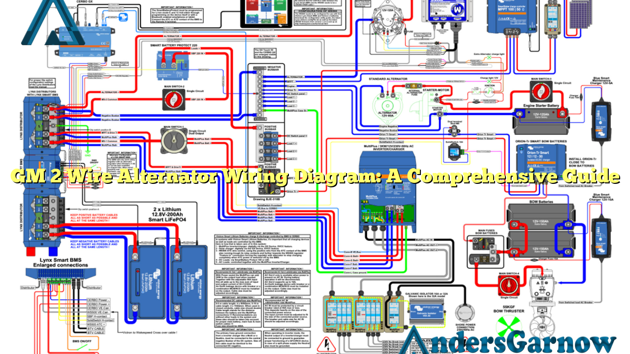
The GM 2 wire alternator wiring diagram is a schematic representation of the electrical connections in a vehicle’s alternator system. It illustrates the specific wiring configuration required for the GM 2 wire alternator setup, which is commonly used in various General Motors vehicles.
This wiring diagram consists of two wires: the main battery wire and the voltage sensing wire. The main battery wire connects the alternator directly to the positive terminal of the battery, while the voltage sensing wire connects the alternator to the ignition switch. This configuration allows the alternator to sense the voltage of the battery and adjust its output accordingly.
Advantages of GM 2 Wire Alternator Wiring Diagram:
- Simple Installation: The GM 2 wire alternator wiring diagram offers a straightforward and easy installation process, making it suitable for DIY enthusiasts.
- Cost-Effective: Compared to other alternator wiring setups, the GM 2 wire system is cost-effective as it requires fewer components.
- Reliable Performance: This wiring diagram provides a reliable charging system for your vehicle, ensuring a steady power supply.
Disadvantages of GM 2 Wire Alternator Wiring Diagram:
- Limitations in Voltage Sensing: The GM 2 wire alternator wiring diagram may not accurately sense the battery voltage in certain situations, leading to potential charging issues.
- Compatibility Constraints: While the GM 2 wire system is commonly used in General Motors vehicles, it may not be compatible with all vehicle models.
2. Alternative Options for GM 2 Wire Alternator Wiring Diagram
If you prefer an alternative to the GM 2 wire alternator wiring diagram, there are a few options to consider:
- GM 1 Wire Alternator Wiring Diagram: The GM 1 wire alternator wiring diagram eliminates the need for a separate voltage sensing wire, simplifying the wiring process.
- Aftermarket Alternator Wiring Kits: Various aftermarket alternator wiring kits are available in the market, providing alternative wiring options for different vehicle models.
3. GM 2 Wire Alternator Wiring Diagram – Detailed Diagram
| Main Battery Wire | Voltage Sensing Wire |
|---|---|
| Connects alternator to positive terminal of the battery | Connects alternator to ignition switch |
FAQs (Frequently Asked Questions)
Q: Can I use the GM 2 wire alternator wiring diagram for any vehicle?
A: While the GM 2 wire system is commonly used in General Motors vehicles, it is essential to check the compatibility with your specific vehicle model before installation.
Q: Are there any safety precautions to consider when working with alternator wiring?
A: Yes, it is crucial to disconnect the negative terminal of the battery before starting any wiring work to prevent electrical shocks or damage to the vehicle’s electrical system.
In Conclusion
The GM 2 wire alternator wiring diagram provides a simple and reliable solution for your vehicle’s charging system. While it has its advantages in terms of cost-effectiveness and ease of installation, there are also limitations to consider. Exploring alternative options, such as the GM 1 wire system or aftermarket wiring kits, can offer different wiring configurations to suit your specific needs. Remember to always prioritize safety when working with electrical systems. Happy wiring!

