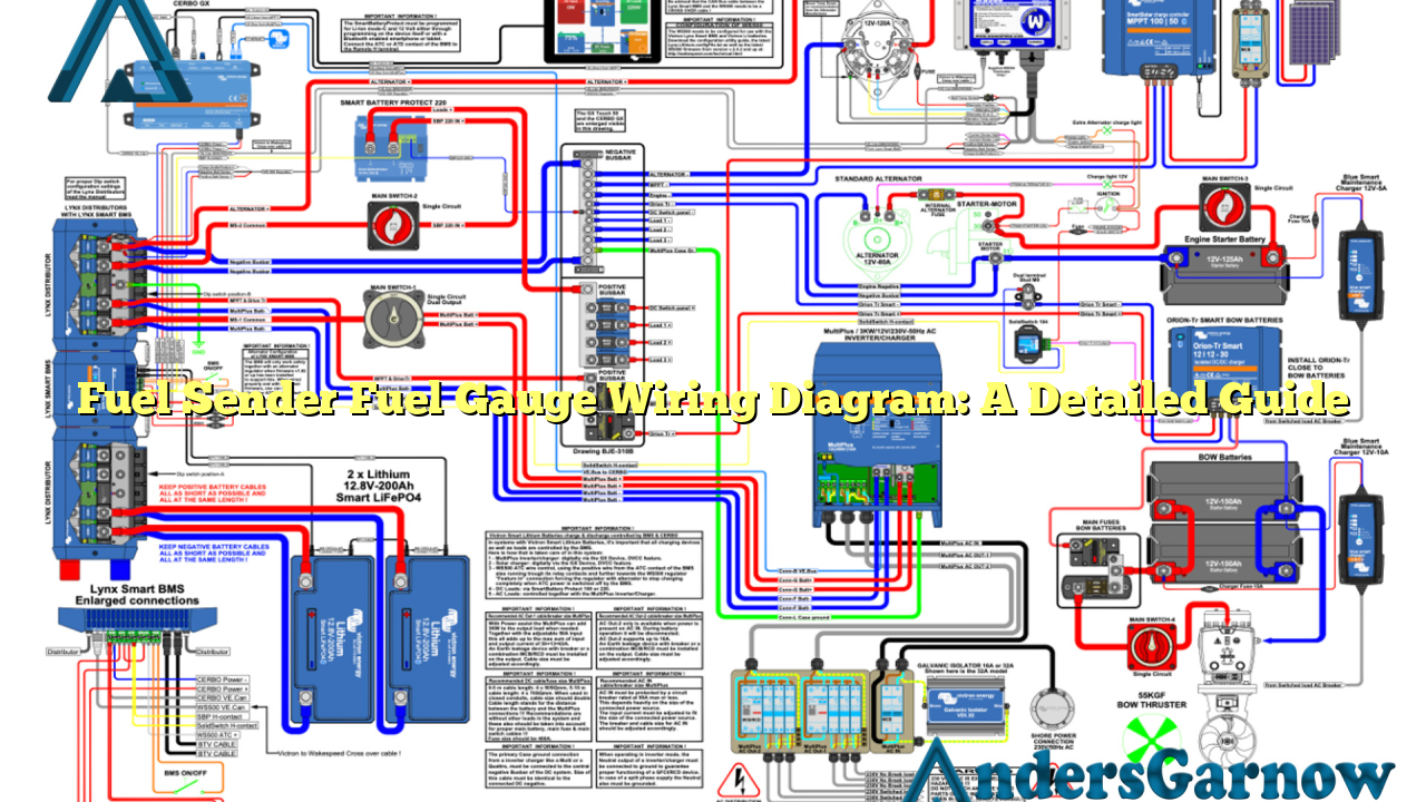
Hello readers! In this article, we will discuss the fuel sender fuel gauge wiring diagram and its importance in the automotive industry. Understanding the wiring diagram is crucial for ensuring the accurate measurement of fuel levels in vehicles. So, let’s dive into the details and explore everything you need to know about fuel sender fuel gauge wiring diagram.
1. Introduction to Fuel Sender Fuel Gauge Wiring Diagram
The fuel sender fuel gauge wiring diagram is a schematic representation of the electrical connections between the fuel sender unit and the fuel gauge in a vehicle. It illustrates the pathway through which the electrical signals travel to provide accurate fuel level readings on the gauge.
The wiring diagram consists of various components such as the fuel sender unit, fuel gauge, power source, ground connection, and wiring harness. Each component plays a vital role in ensuring the proper functioning of the fuel gauge system.
2. Understanding the Components
2.1 Fuel Sender Unit:
The fuel sender unit is responsible for measuring the fuel level in the vehicle’s fuel tank. It consists of a float attached to a variable resistor. As the fuel level changes, the float moves, causing the resistance value to vary.
2.2 Fuel Gauge:
The fuel gauge is the instrument panel component that displays the fuel level to the driver. It receives electrical signals from the fuel sender unit and provides a visual representation of the fuel level through a needle or digital display.
2.3 Power Source and Ground Connection:
The fuel gauge system requires a power source to operate. It is usually connected to the vehicle’s battery or electrical system. The ground connection ensures a complete circuit and enables the flow of electrical signals.
2.4 Wiring Harness:
The wiring harness is a bundle of wires that connects the fuel sender unit, fuel gauge, power source, and ground connection. It acts as a conduit for transmitting electrical signals and ensures a secure and organized connection.
3. Wiring Diagram: Detailed Breakdown
The wiring diagram for the fuel sender fuel gauge system typically consists of color-coded wires and labels for easy identification. Here is a detailed breakdown of the wiring diagram:
| Wire Color | Function |
|---|---|
| Red | Power Source (+) |
| Black | Ground (-) |
| Yellow | Fuel Sender Signal |
| Green | Fuel Gauge Signal |
The red wire connects the fuel gauge to the power source, providing the necessary electrical energy for its operation. The black wire establishes a ground connection, completing the circuit.
The yellow wire carries the fuel sender signal from the fuel sender unit to the fuel gauge. It transmits the varying resistance values based on the fuel level in the tank.
The green wire is responsible for carrying the fuel gauge signal back to the fuel sender unit. This signal helps in calibrating the fuel gauge to provide accurate readings.
4. Advantages of Understanding the Wiring Diagram
4.1 Easy Troubleshooting:
By familiarizing yourself with the fuel sender fuel gauge wiring diagram, you can easily identify any potential issues in the system. This knowledge allows for quick troubleshooting and efficient repairs.
4.2 DIY Modifications:
Understanding the wiring diagram enables you to make DIY modifications to the fuel gauge system. Whether you want to add additional gauges or customize the wiring, having a clear understanding of the diagram is essential.
5. Limitations and Precautions
5.1 Complex Wiring:
The fuel sender fuel gauge wiring diagram can be complex, especially for individuals with limited electrical knowledge. It is recommended to seek professional assistance if you are unsure about any aspect of the wiring diagram.
5.2 Electrical Hazards:
Working with electrical systems can be dangerous. Always ensure that the power source is disconnected before attempting any repairs or modifications. Use proper safety precautions and consult a professional if needed.
6. Alternative Wiring Options
There are various alternative wiring options available for the fuel sender fuel gauge system. These options may differ based on the vehicle’s make, model, and electrical specifications. It is recommended to refer to the vehicle’s wiring diagram or consult a professional for the most accurate and suitable alternative wiring options.
7. Frequently Asked Questions (FAQs)
Q: Can I install a fuel sender fuel gauge system in my vehicle?
A: Yes, it is possible to install a fuel sender fuel gauge system in your vehicle. However, it is recommended to consult a professional for proper installation and compatibility with your vehicle’s electrical system.
Q: How accurate are fuel sender fuel gauges?
A: Fuel sender fuel gauges are generally accurate within a certain range. However, factors such as sensor calibration, fuel tank shape, and vehicle inclination can affect the accuracy of fuel level readings.
Conclusion
In conclusion, the fuel sender fuel gauge wiring diagram is an essential tool for understanding the electrical connections involved in the fuel gauge system. By understanding the diagram, you can troubleshoot issues, make DIY modifications, and ensure the accurate measurement of fuel levels in your vehicle. Remember to exercise caution and seek professional assistance when needed to ensure safety and proper functionality of the system.

