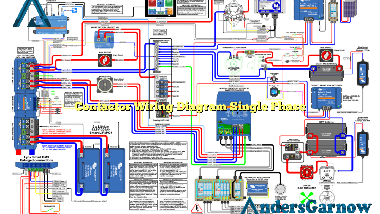
Hello readers! In this article, we will explore the topic of contactor wiring diagram for single-phase electrical systems. A contactor is an electrical device used to control the flow of electricity in a circuit. Understanding the wiring diagram is crucial for proper installation and maintenance of contactors in residential, commercial, and industrial applications.
Subtitles:
1. What is a Contactor?
A contactor is an electromechanical switch that allows or interrupts the flow of electricity in an electrical circuit. It consists of three main components: the contacts, the coil, and the mechanical assembly. The contacts are the parts that physically make or break the electrical connection, while the coil generates a magnetic field to close or open the contacts. The mechanical assembly provides the necessary force to operate the contacts.
2. Single-Phase Contactor Wiring Diagram
When it comes to single-phase contactor wiring, the diagram may vary depending on the specific application and the type of contactor being used. However, there are some common elements that can be found in most single-phase contactor wiring diagrams.
A typical single-phase contactor wiring diagram includes the power supply, the control circuit, the load, and the contactor itself. The power supply provides the electrical energy needed to operate the contactor, while the control circuit controls the operation of the contactor. The load represents the electrical device or equipment that the contactor is controlling.
The contactor is usually represented by a rectangle with two sets of contacts: the main contacts and the auxiliary contacts. The main contacts are used to control the flow of electricity to the load, while the auxiliary contacts are used for auxiliary functions such as signaling or interlocking.
3. Advantages of Using a Contactor
Contactor wiring diagrams are essential for understanding the advantages of using a contactor in electrical systems. Some of the key advantages include:
– Enhanced Safety: Contactors provide a reliable and safe method for controlling electrical circuits. They can handle high currents and voltages, reducing the risk of electrical shock or fire hazards.
– Remote Control: Contactors can be controlled remotely using control signals, allowing for convenient operation and automation of electrical systems.
– Durability: Contactors are designed to withstand frequent switching operations, ensuring long-term reliability and performance.
– Versatility: Contactors can be used in a wide range of applications, from simple residential setups to complex industrial systems.
– Overload Protection: Some contactors come with built-in overload protection features, which help protect electrical devices from damage due to excessive current.
4. Disadvantages of Using a Contactor
While contactors offer many advantages, there are also some disadvantages to consider:
– Complexity: Contactors can be more complex to install and wire compared to simple switches. Proper knowledge and understanding of wiring diagrams are necessary for correct installation.
– Cost: Contactors can be more expensive than traditional switches, especially for high-power applications.
– Maintenance: Contactors may require periodic maintenance to ensure proper functioning and prevent issues such as arcing or contact wear.
5. Alternatives to Contactor Wiring Diagram for Single Phase
While contactors are commonly used in single-phase electrical systems, there are alternative devices that can be used depending on the specific requirements of the application. Some alternatives include:
– Manual Switches: Simple on/off switches can be used for basic control of electrical circuits. However, they lack the advanced features and capabilities offered by contactors.
– Solid-State Relays: Solid-state relays are electronic devices that can perform similar functions to contactors. They use semiconductor technology to control the flow of electricity.
– Motor Starters: Motor starters are specialized contactors designed specifically for controlling electric motors. They provide additional protection features such as overload and short-circuit protection.
6. Contactor Wiring Diagram Single Phase – Complete Guide
To provide a comprehensive guide on contactor wiring diagram for single-phase systems, here is a table summarizing the key components and connections:
| Component | Description |
|---|---|
| Power Supply | Provides electrical energy to the contactor |
| Control Circuit | Controls the operation of the contactor |
| Load | The electrical device or equipment being controlled by the contactor |
| Main Contacts | Controls the flow of electricity to the load |
| Auxiliary Contacts | Used for auxiliary functions such as signaling or interlocking |
7. Frequently Asked Questions (FAQ)
Q: What is the purpose of a contactor in a single-phase electrical system?
A: The purpose of a contactor is to control the flow of electricity to an electrical device or equipment in a single-phase electrical system.
Q: How do I wire a contactor for a single-phase system?
A: Wiring a contactor for a single-phase system requires proper understanding of the wiring diagram provided by the manufacturer. It is recommended to consult a qualified electrician for correct installation.
Q: Can I use a contactor for high-power applications?
A: Yes, contactors are suitable for high-power applications as they can handle high currents and voltages.
Conclusion
In conclusion, understanding the contactor wiring diagram for single-phase electrical systems is essential for proper installation and efficient operation of contactors. Contactors offer numerous advantages, including enhanced safety, remote control capabilities, durability, versatility, and overload protection. However, they may also have some disadvantages, such as complexity, cost, and maintenance requirements. When considering alternatives to contactors, manual switches, solid-state relays, and motor starters can be viable options depending on the specific application requirements. By following the provided wiring diagrams and consulting professionals when needed, you can ensure the reliable and safe operation of your single-phase electrical system.

