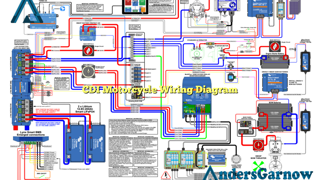
Hello readers! In this article, we will delve into the world of motorcycle wiring diagrams specifically focusing on the Capacitor Discharge Ignition (CDI) system. We will explore the various components, functions, advantages, and disadvantages of CDI motorcycle wiring diagrams. Additionally, we will provide alternative options and a comprehensive table containing all the necessary information. So, let’s dive in!
1. Understanding CDI Motorcycle Wiring Diagram
CDI motorcycle wiring diagrams are essential for understanding the electrical connections and functions of a motorcycle’s ignition system. The CDI system plays a crucial role in controlling the timing of the spark plug and ensuring efficient combustion.
Advantages of CDI Motorcycle Wiring Diagram:
- Improved Ignition Timing: CDI systems offer precise control over the ignition timing, resulting in better fuel efficiency and increased power output.
- Reliable Spark: CDI systems produce a strong and consistent spark, ensuring reliable ignition even in challenging conditions.
- Simple Design: CDI systems have a relatively simple design, making them easy to install and maintain.
Disadvantages of CDI Motorcycle Wiring Diagram:
- Higher Cost: Compared to conventional ignition systems, CDI systems can be more expensive due to the additional electronic components required.
- Compatibility Issues: CDI systems may not be compatible with all motorcycle models, requiring specific wiring modifications or adaptations.
- Expertise Required: Proper installation and troubleshooting of CDI systems may require technical knowledge and expertise.
2. Components of CDI Motorcycle Wiring Diagram
A typical CDI motorcycle wiring diagram consists of several key components:
| Component | Function |
|---|---|
| Stator | Generates electrical power from the engine’s rotation. |
| Trigger Coil | Sends signals to the CDI unit to initiate the ignition process. |
| CDI Unit | Receives signals from the trigger coil and controls the ignition timing. |
| Ignition Coil | Amplifies the voltage from the CDI unit and produces the spark. |
| Spark Plug | Ignites the air-fuel mixture in the combustion chamber. |
3. Alternative Options for Motorcycle Ignition Wiring
While CDI motorcycle wiring diagrams are commonly used, there are alternative options available:
- Points Ignition System: Older motorcycles may use a points-based ignition system, which utilizes mechanical contact points to control the ignition timing.
- Electronic Ignition System: Some modern motorcycles employ advanced electronic ignition systems that utilize microprocessors for precise timing control.
Frequently Asked Questions (FAQ) – CDI Motorcycle Wiring Diagram
Q: Can I install a CDI system on any motorcycle?
A: CDI systems are designed for specific motorcycle models. Compatibility should be checked before installation.
Q: How do I troubleshoot a faulty CDI system?
A: Troubleshooting a faulty CDI system may require professional assistance. However, basic checks include inspecting the wiring connections and testing the components using a multimeter.
Conclusion
In conclusion, understanding the CDI motorcycle wiring diagram is crucial for maintaining and troubleshooting the ignition system of your motorcycle. CDI systems offer advantages such as improved ignition timing and reliable spark, but they may come with higher costs and compatibility issues. By familiarizing yourself with the components and alternatives, you can make informed decisions regarding your motorcycle’s ignition system. Always consult the manufacturer’s guidelines and seek professional help when necessary. Happy riding!

