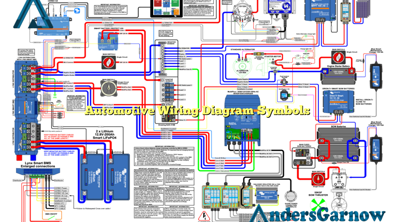
Hello readers! In this article, we will delve into the world of automotive wiring diagram symbols. These symbols are essential for understanding the electrical systems in vehicles, allowing technicians and enthusiasts to diagnose and repair electrical issues effectively. Let’s explore the key symbols and their meanings in detail.
1. Ground Symbol
The ground symbol is represented by a horizontal line intersected by three short vertical lines. It indicates the connection to the vehicle’s chassis, which acts as a common ground point for electrical circuits. This symbol is crucial for identifying grounding points and ensuring proper electrical flow.
Advantages: Ensures stability and safety of electrical circuits.
Disadvantages: None.
2. Battery Symbol
The battery symbol represents the power source in a vehicle, usually a 12-volt automotive battery. It is depicted by a long and short parallel line, with the longer line indicating the positive terminal and the shorter line representing the negative terminal.
Advantages: Provides electrical energy to the entire vehicle.
Disadvantages: None.
3. Fuse Symbol
The fuse symbol is shown as a vertical line with a wavy line crossing it. It represents a protective device that breaks the circuit when excessive current flows, preventing damage to the wiring and components. Fuses are crucial for preventing electrical fires and ensuring system safety.
Advantages: Protects wiring and components from excessive current.
Disadvantages: Requires replacement if blown.
4. Switch Symbol
The switch symbol is represented by a line interrupted by a gap or break. It signifies a device that can open or close a circuit, controlling the flow of electricity. Switches are used to turn on or off various electrical components in a vehicle.
Advantages: Enables control of electrical components.
Disadvantages: None.
5. Resistor Symbol
The resistor symbol is depicted by a zigzag line. It represents a component that restricts the flow of electrical current, regulating voltage levels in a circuit. Resistors are commonly used to control the brightness of lights or the speed of motors.
Advantages: Controls voltage levels and current flow.
Disadvantages: None.
6. Lamp Symbol
The lamp symbol is represented by a circle with a cross inside. It signifies a light source, such as a bulb or LED, used for illumination in a vehicle. This symbol is crucial for identifying lighting circuits and troubleshooting lighting issues.
Advantages: Provides illumination for various applications.
Disadvantages: None.
7. Motor Symbol
The motor symbol is depicted by a circle with a line protruding from it. It represents an electrical motor, which converts electrical energy into mechanical energy to drive various components, such as fans, wipers, or power windows.
Advantages: Powers mechanical components in the vehicle.
Disadvantages: None.
8. Diode Symbol
The diode symbol is shown as a triangle pointing towards a vertical line with an arrowhead. It signifies a semiconductor device that allows current to flow in one direction while blocking it in the opposite direction. Diodes are commonly used in electrical circuits to control current flow and protect sensitive components.
Advantages: Controls current flow and protects components.
Disadvantages: None.
9. Connector Symbol
The connector symbol is depicted as a line with several branches or forks. It represents a point of connection between two or more electrical circuits or components. Connectors are essential for proper electrical connectivity and enable easy removal or replacement of components.
Advantages: Enables easy connection and disconnection of components.
Disadvantages: Possible points of failure if not properly secured.
10. Ground Connection Symbol
The ground connection symbol is represented by a horizontal line intersected by a single vertical line. It indicates the connection to an external ground point, such as the negative terminal of the battery or the vehicle’s chassis. This symbol is used when a separate ground point is required for specific components.
Advantages: Provides a dedicated ground point for components.
Disadvantages: None.
Alternative Wiring Diagram Symbols
While the symbols mentioned above are the most commonly used in automotive wiring diagrams, there may be variations or additional symbols depending on the specific vehicle manufacturer or electrical system design. It is essential to refer to the vehicle’s wiring diagram or consult the manufacturer’s documentation for accurate symbol interpretation.
Automotive Wiring Diagram Symbols Table
| Symbol | Meaning |
|---|---|
| Ground | Connection to the vehicle’s chassis |
| Battery | Power source in the vehicle |
| Fuse | Protective device against excessive current |
| Switch | Device to open or close a circuit |
| Resistor | Component to control voltage levels |
| Lamp | Light source for illumination |
| Motor | Electrical motor for driving components |
| Diode | Device to control current flow |
| Connector | Point of connection between circuits |
| Ground Connection | Connection to an external ground point |
Frequently Asked Questions (FAQ)
Q: Why are wiring diagram symbols important?
A: Wiring diagram symbols provide a standardized way to represent electrical components and connections, making it easier to understand and troubleshoot vehicle electrical systems.
Q: Are automotive wiring diagram symbols the same for all vehicles?
A: While there are common symbols, there may be variations or additional symbols depending on the vehicle manufacturer or electrical system design. Always refer to the specific wiring diagram or manufacturer documentation for accurate symbol interpretation.
Q: Can I repair my vehicle’s electrical system without understanding wiring diagram symbols?
A: It is highly recommended to have a basic understanding of wiring diagram symbols to effectively diagnose and repair electrical issues in vehicles. Without proper knowledge, it can be challenging to identify and troubleshoot problems accurately.
In conclusion
Understanding automotive wiring diagram symbols is crucial for anyone involved in diagnosing and repairing vehicle electrical systems. These symbols provide a universal language for technicians and enthusiasts to communicate and troubleshoot electrical issues effectively. By referring to the wiring diagram and interpreting the symbols correctly, one can ensure the proper functioning and safety of the vehicle’s electrical system.

