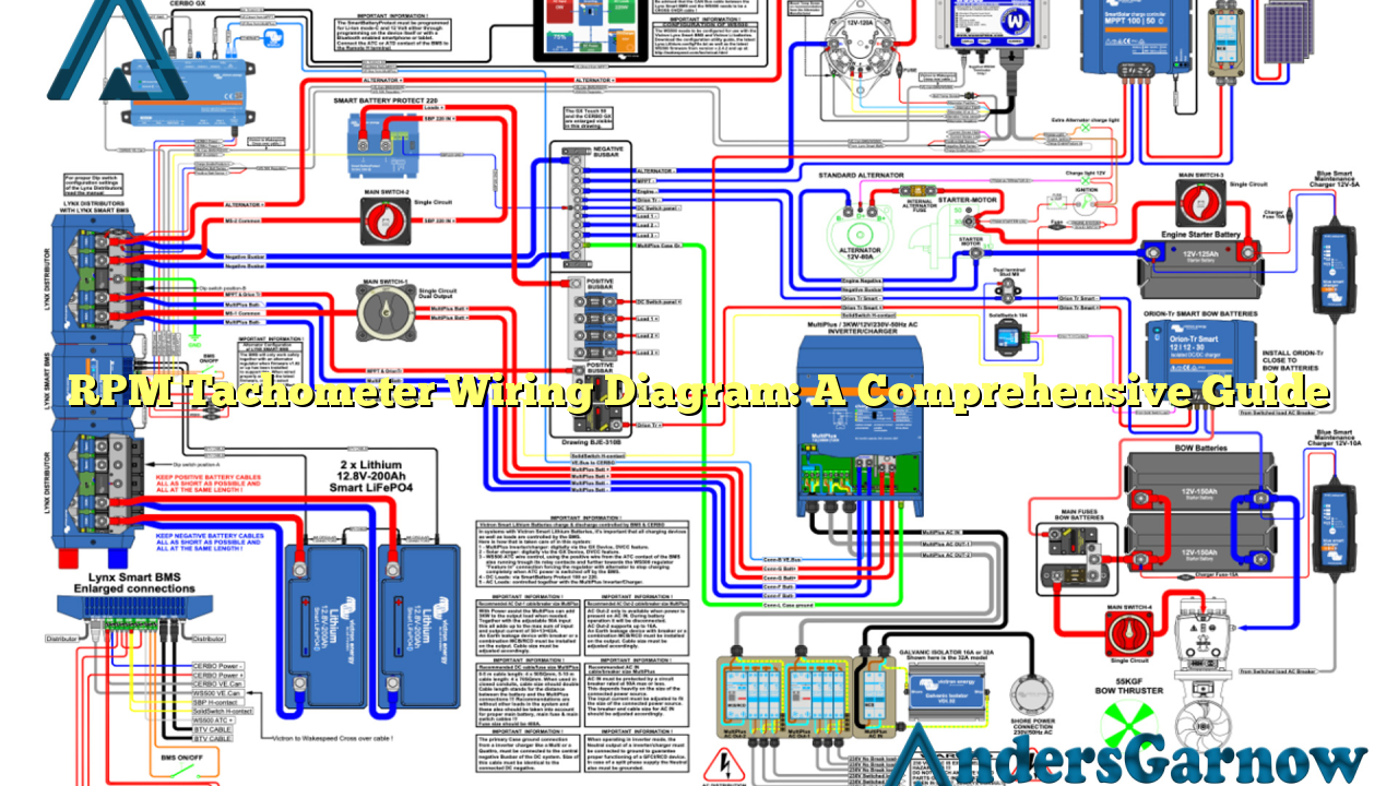
Hello readers! In this article, we will delve into the world of RPM Tachometer Wiring Diagrams, providing you with a detailed and informative guide. Whether you are a seasoned mechanic or a DIY enthusiast, understanding the ins and outs of tachometer wiring diagrams is essential. So, let’s get started!
1. Introduction to RPM Tachometer Wiring Diagrams
RPM Tachometer Wiring Diagrams, also known as rev counters, are instruments used to measure the rotation speed of an engine’s crankshaft. They provide valuable information to drivers and mechanics, enabling them to monitor the engine’s performance and diagnose potential issues.
These diagrams illustrate the connections required to install and connect a tachometer accurately. By following these diagrams, you can ensure a smooth installation process and avoid any complications.
2. The Components of an RPM Tachometer Wiring Diagram
Before we dive into the wiring diagram itself, let’s familiarize ourselves with the key components typically found in an RPM tachometer wiring diagram:
| Component | Description |
|---|---|
| Tachometer | The instrument that displays the engine’s RPM |
| Ignition Coil | An induction coil that converts low voltage from the battery to high voltage for spark plug ignition |
| Distributor | A device that routes high voltage from the ignition coil to the spark plugs in the correct firing order |
| Engine Control Module (ECM) | A computerized control unit that manages various engine functions |
| Power Source | The electrical source that powers the tachometer |
| Ground | A connection point to the vehicle’s chassis, providing a return path for electrical current |
| Signal Wire | The wire that carries the RPM signal from the ignition system to the tachometer |
Understanding these components will facilitate the comprehension of the wiring diagram and simplify the installation process.
3. Wiring Diagram Instructions: Step-by-Step
Now let’s explore the step-by-step instructions to follow when wiring an RPM tachometer:
Step 1: Identify the tachometer’s power source and connect it to a 12V power supply, typically the vehicle’s battery.
Step 2: Locate the ignition coil and identify the wire that carries the RPM signal. This wire is usually color-coded or labeled in the wiring diagram.
Step 3: Connect the RPM signal wire to the corresponding terminal on the tachometer. This connection enables the tachometer to receive the RPM signal.
Step 4: Ground the tachometer by connecting the ground wire to a suitable grounding point on the vehicle’s chassis.
Step 5: If applicable, connect any additional wires specified in the wiring diagram, such as those for lighting or other features.
By following these instructions meticulously, you will successfully wire your RPM tachometer and ensure its accurate functionality.
4. The Pros and Cons of RPM Tachometer Wiring Diagrams
Like any technology, RPM tachometer wiring diagrams have their advantages and disadvantages. Let’s take a closer look:
Pros:
- Allows for precise monitoring of engine RPM for optimal performance
- Enables early detection of potential engine issues
- Facilitates troubleshooting and diagnostics
- Helps maintain engine longevity and prevent damage
- Can be installed in various types of vehicles
Cons:
- Requires proper installation and wiring for accurate readings
- May be challenging for beginners or those unfamiliar with automotive wiring
- Compatibility issues may arise with certain vehicle models
- Relies on the accuracy of the RPM signal from the ignition system
Despite these potential drawbacks, the benefits of using RPM tachometer wiring diagrams outweigh the challenges, making them an indispensable tool for engine enthusiasts and professionals alike.
5. Alternative RPM Tachometer Wiring Diagrams
While the conventional wiring diagrams are widely used, alternative options are available for specific vehicle models or aftermarket tachometers. These alternatives may have variations in wire colors, connector types, or additional features. It is crucial to refer to the specific wiring diagram provided by the tachometer manufacturer or vehicle manufacturer in such cases.
Always ensure that you have the correct wiring diagram for your particular tachometer model and vehicle to avoid any compatibility or functionality issues.
6. Frequently Asked Questions (FAQ)
Q: Can I install an RPM tachometer in any vehicle?
A: RPM tachometers can generally be installed in most vehicles, regardless of make or model, as long as the wiring connections are compatible.
Q: Are there wireless RPM tachometers available?
A: Yes, there are wireless tachometers available that use alternative methods to receive the RPM signal without the need for physical wiring connections.
Q: Do I need professional help to install an RPM tachometer?
A: While professional assistance is not mandatory, it is recommended for individuals with limited knowledge or experience in automotive wiring.
Conclusion
In conclusion, RPM tachometer wiring diagrams play a crucial role in accurately measuring and monitoring an engine’s RPM. By following the step-by-step instructions provided in the wiring diagram, individuals can successfully install a tachometer and benefit from its valuable insights into engine performance. Remember to refer to the specific wiring diagram for your tachometer model and vehicle to ensure a seamless installation process. Happy wiring!

