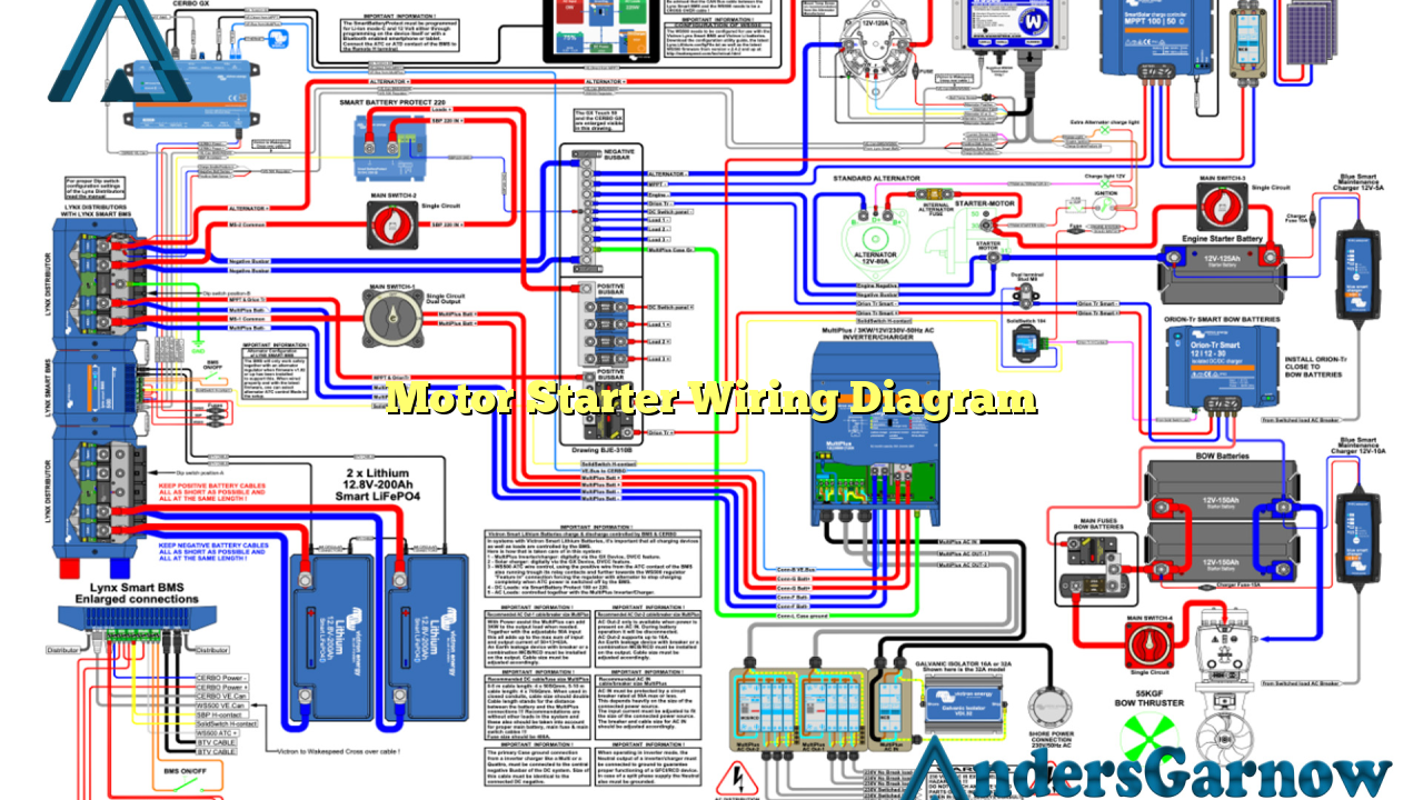
Hello and welcome to this comprehensive article on motor starter wiring diagram. In this guide, we will provide you with detailed information and step-by-step instructions on how to properly wire a motor starter. Whether you are a professional electrician or a DIY enthusiast, this article will help you understand the process and ensure a safe and efficient motor operation.
1. Understanding the Basics of Motor Starter
Before diving into the wiring diagram, it is essential to grasp the fundamentals of a motor starter. A motor starter is an electrical device used to start and stop a motor safely. It consists of several components, including a contactor, overload relay, control circuit, and power circuit. The contactor acts as a switch to connect or disconnect the motor from the power source, while the overload relay protects the motor from excessive current. The control circuit provides the necessary control signals to the contactor, enabling the motor operation.
2. Gathering the Required Tools and Materials
Prior to wiring the motor starter, make sure you have all the necessary tools and materials. This includes a motor starter kit, appropriate wires, wire strippers, screwdrivers, electrical tape, and a voltage tester. It is crucial to have high-quality and properly sized components to ensure a reliable and safe electrical connection.
3. Identifying the Motor Starter Terminals
Before starting the wiring process, it is essential to identify the terminals on the motor starter. Typically, a motor starter will have six terminals: three for power input (L1, L2, L3), and three for motor output (T1, T2, T3). Additionally, there may be terminals for the control circuit, such as the coil terminals (A1, A2) and auxiliary contacts.
4. Wiring the Power Circuit
The power circuit of the motor starter involves connecting the power supply to the motor starter terminals. Start by connecting the power supply wires (L1, L2, L3) to the respective power input terminals. Ensure proper tightness of the connections and use electrical tape to insulate the exposed parts. It is crucial to follow the manufacturer’s instructions and local electrical codes during this process.
5. Wiring the Control Circuit
The control circuit is responsible for sending control signals to the motor starter, enabling its operation. Begin by connecting the control power supply wires (typically 24V) to the coil terminals (A1, A2). Consult the motor starter wiring diagram provided by the manufacturer to determine the specific connections for your motor starter model. Additionally, connect any auxiliary contacts required for specific control functions.
6. Connecting the Motor to the Motor Output Terminals
Now, it’s time to connect the motor to the motor output terminals (T1, T2, T3) of the motor starter. Properly size and strip the motor wires, ensuring they are long enough to reach the terminals without strain. Connect each motor wire to the respective motor output terminal and secure them tightly using screwdrivers. Double-check all connections for tightness and insulation.
7. Testing and Safety Measures
After completing the wiring process, it is vital to test the motor starter before operating the motor. Use a voltage tester to verify the presence of voltage at the motor starter terminals. Additionally, ensure that the control circuit is functioning correctly by testing the control signals. Always follow proper safety measures, such as wearing insulated gloves and de-energizing the circuit before making any adjustments or modifications.
8. Alternative Wiring Methods
While the above wiring method is the most common and widely used, there are alternative wiring methods available for motor starters. These include the use of reversing starters for bidirectional motor operation, star-delta starters for reducing motor starting current, and soft starters for gradual acceleration and deceleration. Each alternative wiring method has its advantages and specific applications, so it is crucial to choose the appropriate method based on your motor and application requirements.
9. Motor Starter Wiring Diagram Table
| Terminal | Description |
|---|---|
| L1, L2, L3 | Power input terminals |
| T1, T2, T3 | Motor output terminals |
| A1, A2 | Coil terminals for control circuit |
| Auxiliary Contacts | Additional control circuit contacts |
10. Frequently Asked Questions (FAQ)
Q: What is the purpose of a motor starter?
A: A motor starter is used to safely start and stop a motor, providing protection against excessive current and ensuring proper motor operation.
Q: Can I use any wire size for motor starter wiring?
A: No, it is crucial to use properly sized wires according to the motor’s current rating and local electrical codes to ensure safe and efficient operation.
Q: Are there any safety precautions I should follow when wiring a motor starter?
A: Yes, always de-energize the circuit before making any wiring connections, wear insulated gloves, and follow the manufacturer’s instructions and local electrical codes.
Conclusion
In conclusion, understanding the motor starter wiring diagram is crucial for proper motor installation and operation. By following the steps outlined in this article and referring to the provided wiring diagram, you can wire a motor starter safely and efficiently. Always prioritize safety and consult professionals if you are unsure about any aspects of the wiring process. With the right knowledge and tools, you can ensure a reliable motor operation for your specific application needs. Good luck!

