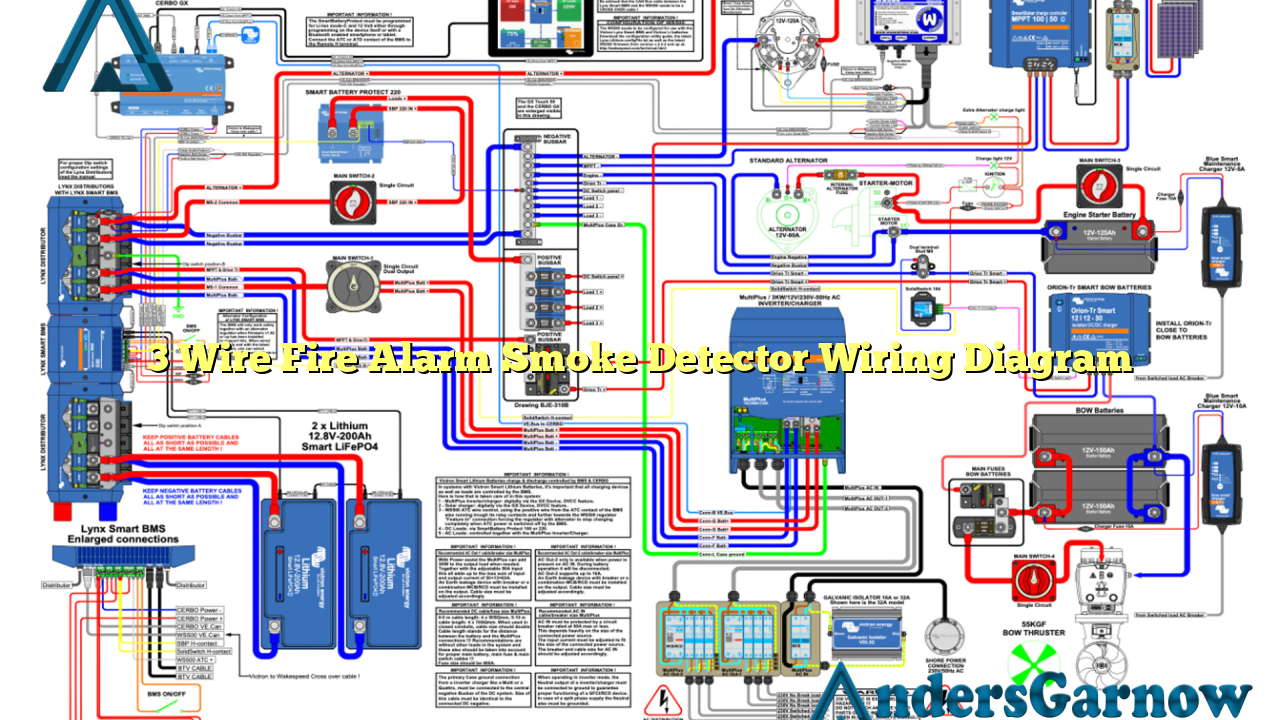
Hello, dear readers! In this article, we will delve into the intricate world of fire alarm systems and explore the 3 wire fire alarm smoke detector wiring diagram. Understanding the wiring diagram is crucial for ensuring the proper installation and functioning of your fire alarm system. So without further ado, let’s dive in!
1. Introduction to Fire Alarm Systems
Fire alarm systems are crucial for the early detection and warning of fires. They consist of various components, including smoke detectors, heat detectors, and control panels. Smoke detectors play a vital role in detecting smoke particles in the air and triggering the alarm.
2. The Importance of Wiring Diagrams
Wiring diagrams provide a visual representation of how the different components of a fire alarm system are connected. They guide installers and technicians in understanding the correct wiring configuration, ensuring a safe and effective system.
3. Understanding the 3 Wire Fire Alarm Smoke Detector Wiring Diagram
The 3 wire fire alarm smoke detector wiring diagram is a commonly used wiring configuration for smoke detectors. It involves three wires: power, signal, and ground. The power wire supplies electrical current to the smoke detector, the signal wire carries the detected smoke signal to the control panel, and the ground wire provides a path for electrical faults.
Advantages of the 3 Wire Fire Alarm Smoke Detector Wiring Diagram
1. Simplicity: The 3 wire configuration simplifies the installation process, reducing the chances of errors and complications.
2. Compatibility: This wiring diagram is compatible with most modern fire alarm systems, making it a versatile choice.
3. Reliability: The separate signal wire ensures a reliable transmission of smoke detection signals to the control panel.
Disadvantages of the 3 Wire Fire Alarm Smoke Detector Wiring Diagram
1. Cost: The 3 wire configuration requires additional wiring materials, increasing the overall cost of the installation.
2. Complexity: Compared to other wiring diagrams, the 3 wire configuration can be more complex to troubleshoot and repair in case of faults.
4. Alternative Wiring Diagram Options
While the 3 wire fire alarm smoke detector wiring diagram is widely used, there are alternative wiring configurations available. One such alternative is the 2 wire configuration, which combines the power and signal wires into a single wire. However, the 2 wire configuration may have limitations in terms of distance and compatibility with certain fire alarm systems.
5. 3 Wire Fire Alarm Smoke Detector Wiring Diagram Table
| Wire | Color | Purpose |
|---|---|---|
| Power | Red | Supplies electrical current to the smoke detector |
| Signal | Yellow | Carries the detected smoke signal to the control panel |
| Ground | Green | Provides a path for electrical faults |
6. Frequently Asked Questions (FAQ)
Q: Can I use a different wire color for the power, signal, and ground?
A: While the standard wire colors are red, yellow, and green, you may use different colors as long as you maintain consistency throughout the installation and document the color-coding for future reference.
Q: Can I mix different wiring configurations in my fire alarm system?
A: It is not recommended to mix different wiring configurations within the same fire alarm system. Stick to a single wiring diagram to ensure compatibility and ease of troubleshooting.
Conclusion
In conclusion, understanding the 3 wire fire alarm smoke detector wiring diagram is essential for a successful installation and efficient functioning of your fire alarm system. While it offers advantages in terms of simplicity and compatibility, it does come with some disadvantages, such as added cost and complexity. Consider your specific requirements and consult with professionals to determine the most suitable wiring diagram for your fire alarm system. Stay safe and protected!

