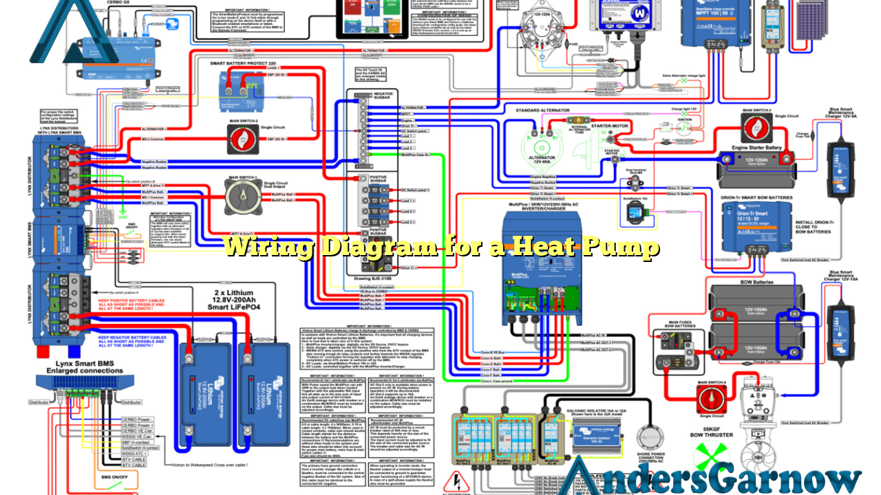
Hello readers, welcome to our article on the wiring diagram for a heat pump. In this article, we will discuss the various components and connections involved in the wiring of a heat pump. Understanding the wiring diagram is crucial for proper installation and troubleshooting of a heat pump system. So, let’s dive into the details!
1. Introduction to Heat Pump Wiring Diagram
A heat pump is an efficient heating and cooling system that transfers heat energy from one place to another. The wiring diagram for a heat pump illustrates the electrical connections between the different components of the system, including the thermostat, compressor, fan motor, reversing valve, and other electrical controls.
2. Thermostat Wiring
The thermostat is the control center of the heat pump system. It senses the temperature and signals the heat pump to turn on or off. The wiring diagram shows the connections between the thermostat and the heat pump unit, including the power supply, heat/cool mode selection, and fan control.
3. Compressor Wiring
The compressor is the heart of the heat pump system. It compresses the refrigerant and circulates it through the system to transfer heat. The wiring diagram illustrates the connections between the compressor, capacitor, and the power supply.
4. Fan Motor Wiring
The fan motor is responsible for circulating air throughout the heat pump system. The wiring diagram shows the connections between the fan motor, capacitor, and the power supply. It also includes the wiring for the high and low-speed settings of the fan motor.
5. Reversing Valve Wiring
The reversing valve controls the direction of the refrigerant flow in a heat pump system. It switches the system between heating and cooling modes. The wiring diagram illustrates the connections between the reversing valve, solenoid, and the thermostat.
6. Electrical Controls Wiring
Heat pumps have various electrical controls to ensure safe and efficient operation. The wiring diagram shows the connections for the pressure switches, temperature sensors, defrost control, and other safety devices.
7. Low Voltage Wiring
The low voltage wiring of a heat pump includes the connections between the thermostat and the heat pump unit. It carries the signals that control the operation of the system. The wiring diagram provides a detailed illustration of the low voltage wiring connections.
8. High Voltage Wiring
The high voltage wiring of a heat pump includes the connections between the power supply and the major components of the system. These connections carry the electrical current that powers the heat pump. The wiring diagram illustrates the high voltage connections in detail.
9. Advantages and Disadvantages of Heat Pump Wiring Diagrams
The advantages of having a wiring diagram for a heat pump are:
- Easy troubleshooting and identification of faulty connections.
- Proper installation of the system, ensuring efficient operation.
- Understanding the electrical controls and safety devices.
The potential disadvantages of heat pump wiring diagrams are:
- Complexity for inexperienced individuals.
- Possibility of misinterpretation or incorrect wiring if not followed carefully.
10. Alternative Wiring Diagrams for Heat Pumps
While the wiring diagram provided here is a standard representation, there may be variations depending on the specific heat pump model and manufacturer. It is always recommended to refer to the manufacturer’s documentation for the most accurate wiring diagram for a particular heat pump model.
Wiring Diagram for a Heat Pump – Complete Information
| Component | Connection |
|---|---|
| Thermostat | Power supply, heat/cool mode, fan control |
| Compressor | Power supply, capacitor |
| Fan Motor | Power supply, capacitor, high/low-speed settings |
| Reversing Valve | Solenoid, thermostat |
| Electrical Controls | Pressure switches, temperature sensors, defrost control |
| Low Voltage Wiring | Thermostat to heat pump unit |
| High Voltage Wiring | Power supply to major components |
Frequently Asked Questions (FAQs)
Q: Why is the wiring diagram important for a heat pump?
A: The wiring diagram helps in understanding the electrical connections of the heat pump system, ensuring proper installation and troubleshooting.
Q: Can I use a generic wiring diagram for any heat pump model?
A: While the basic principles are similar, it is always recommended to refer to the specific wiring diagram provided by the heat pump manufacturer.
Q: Are there any safety precautions to consider while working with the wiring diagram?
A: Yes, it is important to turn off the power supply before working on any electrical connections and to follow all safety guidelines provided by the manufacturer.
Conclusion
In conclusion, understanding the wiring diagram for a heat pump is crucial for proper installation, troubleshooting, and efficient operation of the system. It allows for easy identification of connections and ensures the safety of the electrical controls. While the diagram provided here is a standard representation, it is important to refer to the manufacturer’s documentation for the most accurate wiring diagram for a specific heat pump model. Always follow safety precautions and consult a professional if needed. Stay informed and enjoy the benefits of a well-wired heat pump system!

