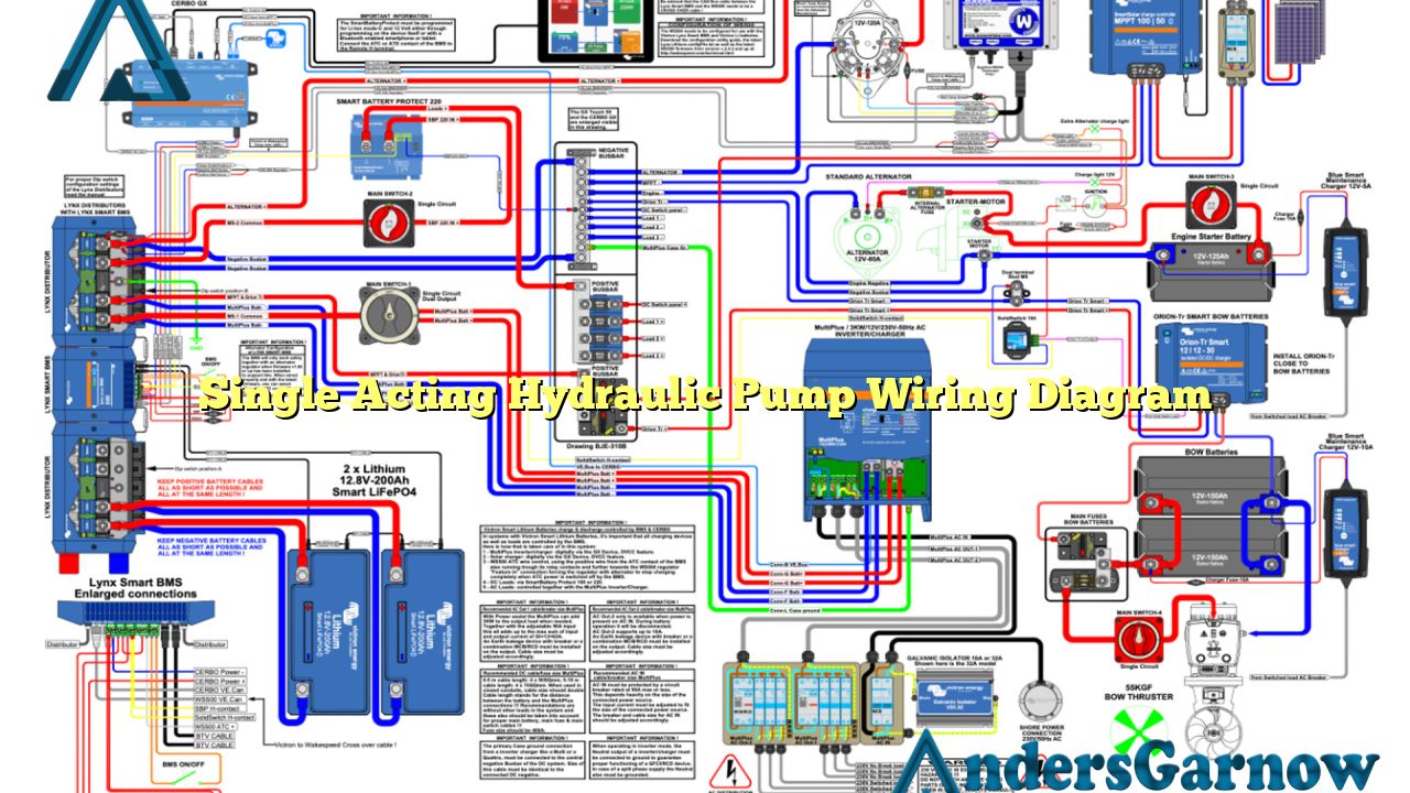
Hello readers! In this article, we will dive into the intricate details of a single acting hydraulic pump wiring diagram. Hydraulic pumps play a crucial role in various industries such as construction, manufacturing, and transportation. Understanding the wiring diagram is essential for proper installation and maintenance. So, let’s explore the components, advantages, disadvantages, and alternative options of a single acting hydraulic pump wiring diagram.
1. Introduction to Single Acting Hydraulic Pump Wiring Diagram
A single acting hydraulic pump is a type of pump that delivers hydraulic fluid under pressure to perform work in one direction. The wiring diagram provides a visual representation of the electrical connections required for the pump’s operation. It includes components such as power supply, control switches, solenoid valves, and motor connections.
2. Components of Single Acting Hydraulic Pump Wiring Diagram
The key components of a single acting hydraulic pump wiring diagram are:
| Component | Description |
|---|---|
| Power Supply | Provides electrical energy to the pump system. |
| Control Switches | Allow manual control of the pump’s operation. |
| Solenoid Valves | Regulate the flow of hydraulic fluid in the system. |
| Motor Connections | Connect the pump motor to the power supply. |
3. Advantages of Single Acting Hydraulic Pump Wiring Diagram
The advantages of using a single acting hydraulic pump wiring diagram include:
- Simplified installation process
- Clear understanding of electrical connections
- Easy troubleshooting and maintenance
- Enhanced safety during operation
4. Disadvantages of Single Acting Hydraulic Pump Wiring Diagram
Despite its advantages, there are a few disadvantages of using a single acting hydraulic pump wiring diagram:
- Limited functionality for complex hydraulic systems
- Higher chances of electrical failures
- Requires periodic inspection and maintenance
5. Alternative Options for Single Acting Hydraulic Pump Wiring Diagram
If a single acting hydraulic pump wiring diagram does not meet your requirements, you can consider alternative options such as:
- Double acting hydraulic pump wiring diagram
- Variable displacement hydraulic pump wiring diagram
- Electronic control unit-based hydraulic pump wiring diagram
6. Frequently Asked Questions (FAQ) about Single Acting Hydraulic Pump Wiring Diagram
Q: Can I use a single acting hydraulic pump for both directions of work?
A: No, a single acting hydraulic pump is designed to perform work in one direction only.
Q: How can I ensure the safety of the wiring connections?
A: It is recommended to follow the manufacturer’s guidelines and consult a professional for proper installation.
Q: What are the common causes of electrical failures in a hydraulic pump system?
A: Common causes include loose connections, damaged wires, and power supply issues.
Conclusion
In conclusion, understanding the single acting hydraulic pump wiring diagram is crucial for successful installation and maintenance. It simplifies the process, provides clarity on electrical connections, and enhances safety during operation. However, it is essential to consider the limitations and explore alternative options based on your specific requirements. Always follow the manufacturer’s guidelines and seek professional assistance when needed to ensure a reliable hydraulic pump system.

