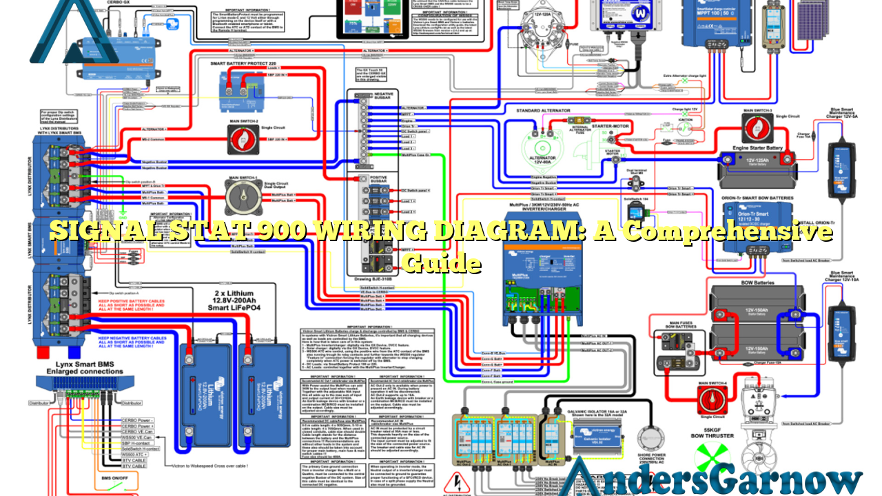
Hello readers, today we will be exploring the ins and outs of the Signal Stat 900 wiring diagram. This article aims to provide you with a detailed understanding of this wiring diagram and its components. Whether you are a novice or an expert, this guide will help you navigate through the intricacies of the Signal Stat 900 wiring diagram.
1. Introduction to Signal Stat 900
The Signal Stat 900 is a widely-used and reliable wiring diagram in the automotive industry. It is commonly used for vehicles that require a turn signal switch and emergency flasher. The diagram provides a clear and systematic layout of the wiring connections, making it easier for technicians and enthusiasts to understand and troubleshoot.
2. Understanding the Components
The Signal Stat 900 wiring diagram consists of various components, including the turn signal switch, flasher, fuse panel, brake switch, and wires connecting them. Each component plays a crucial role in ensuring the proper functioning of the vehicle’s turn signals and emergency flashers.
2.1 Turn Signal Switch
The turn signal switch is the main control mechanism for the vehicle’s turn signals. It allows the driver to indicate their intention to turn or change lanes by activating the appropriate signals. The Signal Stat 900 wiring diagram clearly illustrates the wiring connections for the turn signal switch.
2.2 Flasher
The flasher is responsible for controlling the flashing speed of the turn signals and emergency flashers. It ensures that the signals blink at a consistent and appropriate rate. The Signal Stat 900 wiring diagram provides the necessary information to properly connect the flasher to the vehicle’s electrical system.
2.3 Fuse Panel
The fuse panel protects the electrical circuits from overload and short circuits. It contains multiple fuses that can be easily replaced if a circuit malfunctions. The wiring diagram highlights the fuse panel’s location and the corresponding fuses for the turn signals and emergency flashers.
2.4 Brake Switch
The brake switch is an important component that activates the brake lights when the brake pedal is pressed. The Signal Stat 900 wiring diagram clearly depicts the connection between the brake switch and the turn signal switch, ensuring proper synchronization between the brake lights and turn signals.
3. Advantages and Disadvantages of Signal Stat 900 Wiring Diagram
The Signal Stat 900 wiring diagram offers several advantages, including:
- Clear and systematic layout for easy understanding
- Comprehensive information on various components
- Facilitates troubleshooting and repairs
- Widely used and reliable in the automotive industry
However, there are a few disadvantages to consider:
- May require technical knowledge to interpret
- Specific to the Signal Stat 900 model
- Not suitable for all vehicle makes and models
4. Alternative Wiring Diagrams
While the Signal Stat 900 wiring diagram is widely used, there are alternative wiring diagrams available for different vehicles. Some popular alternatives include the Universal Turn Signal Switch wiring diagram and the Vintage Auto Garage Turn Signal Switch wiring diagram. It is essential to choose the appropriate wiring diagram based on your vehicle’s make and model.
5. Signal Stat 900 Wiring Diagram Table
| Component | Connection |
|---|---|
| Turn Signal Switch | Connect to steering column |
| Flasher | Connect to turn signal switch and fuse panel |
| Fuse Panel | Connect to battery and various electrical components |
| Brake Switch | Connect to turn signal switch |
6. Frequently Asked Questions (FAQ)
Q: What vehicles is the Signal Stat 900 wiring diagram compatible with?
A: The Signal Stat 900 wiring diagram is compatible with a wide range of vehicles that require a turn signal switch and emergency flasher. However, it is essential to consult the specific wiring diagram for your vehicle’s make and model.
Q: Can I use the Signal Stat 900 wiring diagram for other turn signal switches?
A: The Signal Stat 900 wiring diagram is specifically designed for the Signal Stat 900 model. It may not be compatible with other turn signal switches. It is recommended to refer to the appropriate wiring diagram for your specific turn signal switch.
Q: How can I troubleshoot issues with the turn signals using the Signal Stat 900 wiring diagram?
A: The Signal Stat 900 wiring diagram provides a clear layout of the wiring connections. By following the diagram, you can identify any faulty connections or components that may be causing issues with the turn signals. Additionally, you can use a multimeter to test the continuity of the wires and ensure proper electrical flow.
Conclusion
In conclusion, the Signal Stat 900 wiring diagram is an invaluable tool for anyone working with turn signals and emergency flashers. Its comprehensive layout and detailed information make troubleshooting and repairs more accessible. However, it is crucial to ensure compatibility with your specific vehicle make and model. By referring to the wiring diagram and understanding its components, you can effectively maintain and troubleshoot your vehicle’s turn signals with ease.

