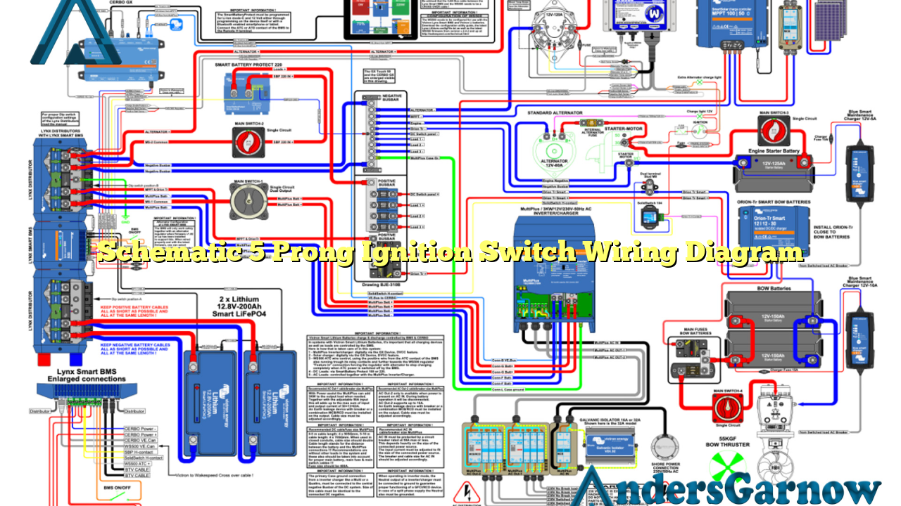
Hello and welcome to our comprehensive guide on the schematic 5 prong ignition switch wiring diagram. In this article, we will explore the intricacies of this wiring diagram and provide you with all the information you need to know. Whether you are a professional mechanic or a passionate DIY enthusiast, this article will serve as your go-to resource for understanding and implementing the schematic 5 prong ignition switch wiring diagram.
1. Understanding the Basics
Before diving into the details, let’s start by understanding the basics of the schematic 5 prong ignition switch wiring diagram. This diagram is a visual representation of the electrical connections and functions of a 5 prong ignition switch. It provides a clear and organized layout of how the different wires should be connected to ensure proper ignition system operation.
The 5 prong ignition switch typically consists of five terminals labeled: BAT, ACC, IGN, ST, and SOL. Each terminal has a specific purpose and must be connected correctly to ensure the ignition switch functions as intended.
Terminal Labels:
| Terminal | Purpose |
|---|---|
| BAT | Connects to the positive terminal of the battery to supply power to the ignition switch. |
| ACC | Connects to accessories such as radios, lights, and other electrical components that require power when the ignition is in the ACC or ON position. |
| IGN | Connects to the ignition coil or ignition control module to provide power when the ignition switch is in the ON and START positions. |
| ST | Connects to the starter solenoid to activate the starter motor when the ignition switch is in the START position. |
| SOL | Connects to the starter solenoid to control the flow of current from the battery to the starter motor. |
Now that we have a basic understanding of the terminal labels, let’s move on to the wiring details and explore the connections in more detail.
2. Wiring Connections
The schematic 5 prong ignition switch wiring diagram consists of various wire connections that must be made for proper functionality. Each wire serves a specific purpose and must be correctly connected to ensure the ignition system operates smoothly.
Wire Connections:
| Terminal | Wire Color | Connection |
|---|---|---|
| BAT | Red | Connects to the positive terminal of the battery. |
| ACC | Yellow | Connects to accessories such as radios, lights, and other electrical components. |
| IGN | Pink | Connects to the ignition coil or ignition control module. |
| ST | Purple | Connects to the starter solenoid. |
| SOL | Orange | Connects to the starter solenoid. |
It is crucial to ensure that the wires are securely connected and insulated to prevent any electrical malfunctions or short circuits. Properly crimping and soldering the connections, as well as using heat shrink tubing, is recommended to ensure a reliable and durable wiring setup.
3. Advantages and Disadvantages
The schematic 5 prong ignition switch wiring diagram offers several advantages, including:
- Clear and organized representation of the ignition switch connections.
- Easy identification of wire colors and terminal labels.
- Ensures proper functionality of the ignition system.
- Facilitates troubleshooting and diagnostics.
However, it is essential to consider the disadvantages as well:
- Requires basic knowledge of automotive electrical systems.
- Incorrect wiring connections can lead to ignition system failure.
- May vary depending on the specific vehicle make and model.
It is always recommended to refer to the vehicle’s service manual or consult with a professional mechanic to ensure the correct wiring connections for your specific vehicle.
4. Alternative Wiring Diagrams
While the schematic 5 prong ignition switch wiring diagram is widely used, there are alternative wiring diagrams available. These alternatives may vary in terms of wire colors and terminal labels, but the overall concept remains the same.
Some common alternatives include:
- 4 prong ignition switch wiring diagram.
- 6 prong ignition switch wiring diagram.
- Universal ignition switch wiring diagram.
It is important to note that before using an alternative wiring diagram, it is necessary to understand the specific terminal labels and wire connections for that particular diagram.
5. Frequently Asked Questions (FAQ)
Here are some frequently asked questions about the schematic 5 prong ignition switch wiring diagram:
Q: Can I use different wire colors for the connections?
A: While the wire colors mentioned in the wiring diagram are commonly used, you can use different colors as long as you ensure proper connections and labeling.
Q: What should I do if I encounter difficulties during the wiring process?
A: If you face any difficulties, it is recommended to consult the vehicle’s service manual or seek assistance from a professional mechanic.
Q: Can I replace the ignition switch myself?
A: Replacing the ignition switch requires advanced knowledge and skills. It is recommended to seek professional help to ensure proper installation and functionality.
Conclusion
In conclusion, the schematic 5 prong ignition switch wiring diagram is a vital tool for understanding and implementing the correct wiring connections for your vehicle’s ignition system. By following the diagram and ensuring proper wire connections, you can ensure the reliable and efficient operation of your ignition switch. Remember to exercise caution and refer to the vehicle’s service manual or consult with a professional mechanic if you encounter any difficulties. Happy wiring!

