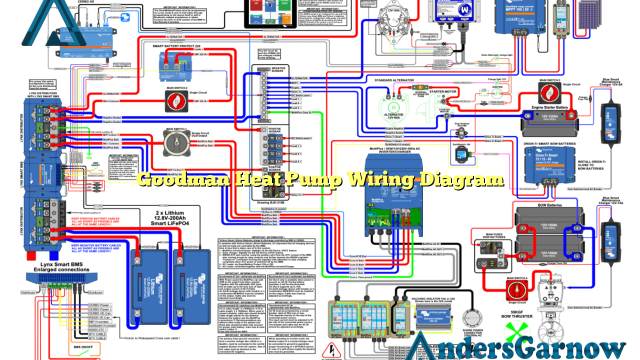
Hello readers! In this article, we will dive into the world of Goodman heat pump wiring diagrams. A heat pump is an essential component of any heating and cooling system, and understanding its wiring diagram is crucial for proper installation and troubleshooting. So, let’s explore the ins and outs of the Goodman heat pump wiring diagram in detail.
1. Introduction to Goodman Heat Pump Wiring Diagram
The Goodman heat pump wiring diagram is a graphical representation of the electrical connections and wiring scheme of a Goodman heat pump system. It illustrates how the various components, such as the compressor, condenser fan motor, reversing valve, and thermostat, are interconnected to ensure the heat pump operates effectively.
A well-designed wiring diagram simplifies the installation process and helps technicians identify and troubleshoot any potential issues. It provides a clear understanding of the electrical connections and ensures that the heat pump system functions optimally.
2. Components of the Goodman Heat Pump Wiring Diagram
The Goodman heat pump wiring diagram consists of several key components:
| Component | Description |
|---|---|
| Compressor | The main component responsible for compressing the refrigerant and circulating it through the heat pump system. |
| Condenser Fan Motor | Helps dissipate heat from the refrigerant by blowing air over the condenser coils. |
| Reversing Valve | Controls the direction of refrigerant flow to switch between heating and cooling modes. |
| Thermostat | Regulates the temperature and controls the operation of the heat pump system. |
These components work together to ensure efficient heating and cooling in your home or office.
3. Detailed Explanation of the Goodman Heat Pump Wiring Diagram
Now, let’s delve into the details of each component in the Goodman heat pump wiring diagram:
Compressor
The compressor is the heart of the heat pump system. It is responsible for compressing the refrigerant, raising its temperature, and circulating it through the system. The compressor is connected to the power supply and is controlled by the thermostat. The wiring diagram shows the electrical connections of the compressor, including the start and run capacitors, as well as the common, run, and start terminals.
Condenser Fan Motor
The condenser fan motor plays a vital role in dissipating heat from the refrigerant. It blows air over the condenser coils, helping to cool down the refrigerant so that it can absorb heat from the indoor air. The wiring diagram illustrates the connections of the condenser fan motor, including the common, fan, and capacitor terminals.
Reversing Valve
The reversing valve is responsible for changing the direction of refrigerant flow, allowing the heat pump to switch between heating and cooling modes. The wiring diagram shows how the reversing valve is connected to the power supply and the thermostat, ensuring proper functionality.
Thermostat
The thermostat is the control center of the heat pump system. It senses the temperature and signals the heat pump to heat or cool the space accordingly. The wiring diagram displays the connections of the thermostat, including the power supply, heat pump terminals, and auxiliary heat terminals.
4. Advantages of the Goodman Heat Pump Wiring Diagram
The Goodman heat pump wiring diagram offers several advantages:
- Easy installation: The wiring diagram provides a clear and concise representation of the electrical connections, making installation hassle-free.
- Troubleshooting made simple: In case of any issues, the wiring diagram allows technicians to quickly identify and rectify the problem, minimizing downtime.
- Optimal performance: Proper wiring ensures that the heat pump system operates at its maximum efficiency, providing comfortable heating and cooling.
5. Disadvantages of the Goodman Heat Pump Wiring Diagram
While the Goodman heat pump wiring diagram has numerous benefits, it is essential to consider its limitations:
- Complexity: Understanding and interpreting the wiring diagram requires technical knowledge and expertise.
- Specificity: The wiring diagram is specific to Goodman heat pump systems and may not be applicable to other brands or models.
- Noise: The wiring diagram does not address noise-related issues that may arise from the heat pump system.
6. Alternative Wiring Diagrams for Goodman Heat Pumps
Aside from the standard Goodman heat pump wiring diagram, there are alternative options available. These alternative wiring diagrams cater to specific installation requirements or system configurations.
Some common alternative wiring diagrams include:
- Dual Fuel Wiring Diagram: Suitable for heat pump systems with an additional gas furnace for auxiliary heating.
- Two-Stage Wiring Diagram: Designed for heat pump systems with two-stage compressors for enhanced efficiency.
- Zoned System Wiring Diagram: Ideal for heat pump systems with multiple zones, allowing independent temperature control in different areas.
It is crucial to consult the manufacturer’s guidelines or a qualified technician to determine the appropriate wiring diagram for your specific heat pump system.
7. Frequently Asked Questions (FAQ) about Goodman Heat Pump Wiring Diagram
Q: Can I use the same wiring diagram for different Goodman heat pump models?
A: While the basic wiring principles remain the same, some differences may exist between models. Always refer to the specific wiring diagram provided by Goodman for your heat pump model.
Q: Is it necessary to hire a professional for heat pump installation?
A: Heat pump installation involves complex electrical and refrigerant connections. It is recommended to hire a qualified technician to ensure proper installation and avoid any safety hazards.
Q: Can I modify the wiring diagram to suit my needs?
A: Modifying the wiring diagram without proper knowledge and expertise can result in system malfunctions or damage. It is best to consult a professional before making any modifications.
Conclusion
In conclusion, understanding the Goodman heat pump wiring diagram is crucial for a successful installation and optimal performance of your heat pump system. This comprehensive guide has provided an overview of the components, advantages, and limitations of the wiring diagram. Remember to consult the manufacturer’s guidelines or seek professional assistance for any specific requirements or modifications. With the right wiring diagram in hand, you can enjoy efficient heating and cooling for your home or office.

