Hello readers,
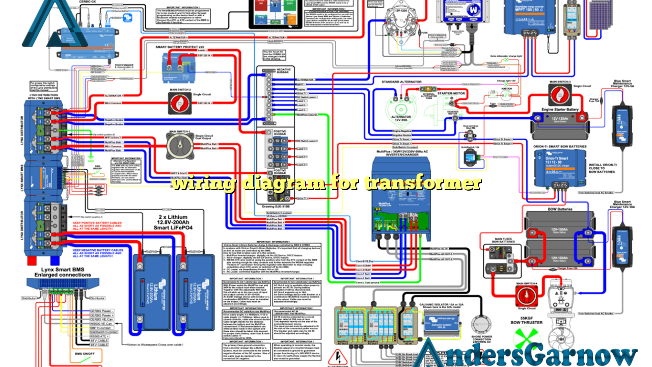
In this article, we will discuss the wiring diagram for transformers. A transformer is an electrical device that transfers electrical energy between two or more circuits through electromagnetic induction. It is an essential component in various electrical systems, including power distribution networks, industrial machinery, and electronic devices.
1. Understanding the Basics of Transformers
Before diving into the wiring diagram, let’s first understand the basics of transformers. A transformer consists of two coils, known as primary and secondary, which are wound around a core. The primary coil receives electrical energy, while the secondary coil delivers the transformed electrical energy.
The primary coil is connected to an alternating current (AC) power source, while the secondary coil is connected to the load. The core, usually made of iron or steel, provides a path for the magnetic flux generated by the alternating current in the primary coil.
Advantages and Disadvantages of Transformers
Transformers offer several advantages:
- Efficient energy transfer: Transformers have high efficiency, resulting in minimal power loss during energy transfer.
- Voltage regulation: Transformers can step up or step down the voltage levels, allowing for efficient power distribution.
- Isolation: Transformers provide electrical isolation between the primary and secondary circuits, ensuring safety.
However, transformers also have some limitations:
- Size and weight: Transformers can be bulky and heavy, especially for high-power applications.
- Cost: Transformers, especially those designed for high voltage and power, can be expensive.
2. Wiring Diagram for a Step-Down Transformer
A step-down transformer is a type of transformer that decreases the voltage level. It is commonly used in residential and commercial applications to match the voltage requirements of appliances. The wiring diagram for a step-down transformer typically includes the following components:
- Primary winding: This is the coil connected to the high-voltage power supply.
- Secondary winding: This is the coil connected to the load or the device requiring a lower voltage.
- Core: The core provides a path for the magnetic flux generated by the alternating current.
The primary winding is connected to the AC power source, while the secondary winding is connected to the load. The wiring diagram specifies the number of turns for each winding and the configuration (e.g., center-tapped or non-center-tapped).
3. Wiring Diagram for a Step-Up Transformer
A step-up transformer is a type of transformer that increases the voltage level. It is commonly used in power transmission and distribution systems to minimize power loss during long-distance electricity transportation. The wiring diagram for a step-up transformer includes similar components as a step-down transformer:
- Primary winding
- Secondary winding
- Core
The primary winding is connected to the power source, while the secondary winding is connected to the load or the power transmission line. The wiring diagram specifies the number of turns for each winding and the configuration.
4. Alternative Wiring Diagram for Transformers
In addition to the conventional wiring diagrams, there are alternative wiring configurations for transformers. These configurations include:
- Delta-Wye (Δ-Y) configuration
- Wye-Delta (Y-Δ) configuration
- Autotransformer configuration
Each configuration offers specific advantages and is suitable for different applications. The choice of wiring diagram depends on factors such as power requirements, voltage levels, and electrical system design.
5. Complete Wiring Diagram for Transformers
Here is a table summarizing the complete wiring diagram for transformers:
| Component | Description |
|---|---|
| Primary winding | Coil connected to the high-voltage power source |
| Secondary winding | Coil connected to the load or device |
| Core | Provides a path for magnetic flux |
This table provides a concise overview of the main components of a transformer’s wiring diagram.
6. Frequently Asked Questions (FAQ)
Q: What is the purpose of a transformer?
A: The purpose of a transformer is to transfer electrical energy between two or more circuits through electromagnetic induction.
Q: Can a transformer be used to increase or decrease the frequency of the power supply?
A: No, transformers cannot change the frequency of the power supply. They can only change the voltage level.
Q: Are transformers only used in power distribution systems?
A: No, transformers are also used in various electronic devices, such as computers, televisions, and audio equipment.
Conclusion
In conclusion, understanding the wiring diagram for transformers is crucial for proper installation and operation of these electrical devices. Whether it’s a step-down or step-up transformer, the wiring diagram provides essential information about the configuration and connections of the primary and secondary windings. Additionally, alternative wiring configurations and complete diagrams help cater to different power requirements and system designs. Transformers play a vital role in power distribution, voltage regulation, and electrical isolation, offering numerous advantages despite their size and cost limitations.

