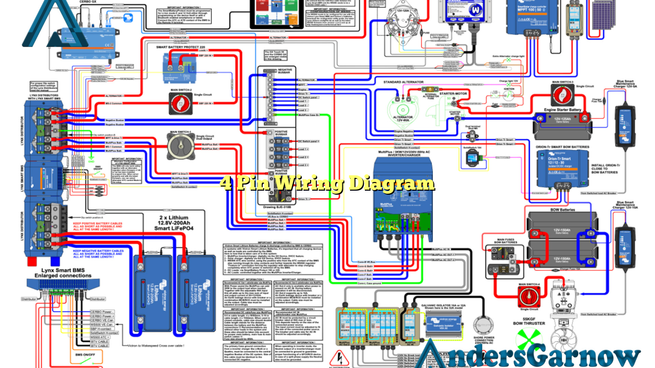
Hello readers! In this article, we will delve into the fascinating world of 4 pin wiring diagrams. Whether you are a seasoned electrician or a curious DIY enthusiast, understanding the intricacies of these diagrams is vital for successfully connecting electrical devices. So, let’s dive in and explore the ins and outs of 4 pin wiring diagrams.
1. What is a 4 Pin Wiring Diagram?
A 4 pin wiring diagram is a graphical representation of the electrical connections between various components or devices in a circuit. It uses standardized symbols to depict the flow of electricity and the connections between pins or terminals. These diagrams are widely used in the automotive industry, home appliances, and electronic devices.
Advantages of 4 Pin Wiring Diagrams:
1. Easy to understand: 4 pin wiring diagrams use standardized symbols, making them easy to interpret and understand by professionals and beginners alike.
2. Clear visualization: These diagrams provide a clear visual representation of the circuit connections, making troubleshooting and repairs more efficient.
3. Consistent format: 4 pin wiring diagrams follow a consistent format, allowing for easy comparison and analysis of different circuits.
Disadvantages of 4 Pin Wiring Diagrams:
1. Complexity: Some 4 pin wiring diagrams can be complex, especially in circuits with numerous components or intricate connections.
2. Limited information: While these diagrams provide a visual representation of the connections, they may not include detailed information about component specifications or functionality.
3. Dependence on accuracy: Any inaccuracies or errors in the diagram can lead to incorrect connections, potentially causing electrical malfunctions or hazards.
2. Understanding the Components
Before we delve deeper into 4 pin wiring diagrams, let’s familiarize ourselves with the key components commonly encountered in these diagrams:
| Component | Description |
|---|---|
| Power Source | The source of electrical power for the circuit. |
| Ground | A reference point for voltages in the circuit. |
| Switch | A device that controls the flow of electricity in the circuit. |
| Load | An electrical device or component that consumes power. |
3. Common Wiring Configurations
There are several common wiring configurations used in 4 pin wiring diagrams:
a. Series Wiring
In series wiring, the components are connected one after another in a single path. The current flows through each component in the circuit.
b. Parallel Wiring
In parallel wiring, the components are connected across multiple paths. The current splits and flows through each component simultaneously.
c. Combination Wiring
Combination wiring involves a combination of series and parallel connections. This allows for more complex circuits and diverse functionality.
4. Alternative to 4 Pin Wiring Diagrams
While 4 pin wiring diagrams are widely used, there are alternative methods to represent circuit connections, such as:
1. Written Descriptions: Instead of using graphical diagrams, written descriptions can be used to explain the connections and provide step-by-step instructions.
2. Photographic Documentation: Photographs or images can be used to visually document the connections in a circuit.
3. Virtual Simulations: With the aid of software or online tools, virtual simulations can be created to demonstrate the circuit connections and their functionality.
5. Frequently Asked Questions (FAQ)
Q: Can I use a 4 pin wiring diagram for any electrical circuit?
A: 4 pin wiring diagrams are commonly used for various applications, but it’s important to ensure that the diagram matches the specific circuit requirements and components.
Q: Are 4 pin wiring diagrams universal?
A: While the symbols and conventions used in 4 pin wiring diagrams are generally standardized, variations may exist based on different industries or regions.
Q: How can I ensure the accuracy of a 4 pin wiring diagram?
A: Double-checking the diagram with reliable sources, such as equipment manuals or consulting professionals, can help ensure its accuracy.
In conclusion
4 pin wiring diagrams provide a crucial visual representation of circuit connections. They offer a standardized and clear way to understand and troubleshoot electrical devices. However, they require accuracy and may be complex in certain situations. Understanding the components and common wiring configurations is essential for working with these diagrams effectively. Consider alternatives when appropriate, and always refer to reliable sources for accurate information. Happy wiring!

