Hello readers!
1. Introduction
Capacitors are essential components in electrical and electronic circuits. They store and release electrical energy, providing power and stability to various devices. Understanding the wiring diagram for capacitors is crucial for proper installation and troubleshooting. In this article, we will explore the different aspects of capacitor wiring diagrams, including their advantages, disadvantages, and alternative options.
2. Understanding Capacitor Wiring Diagrams
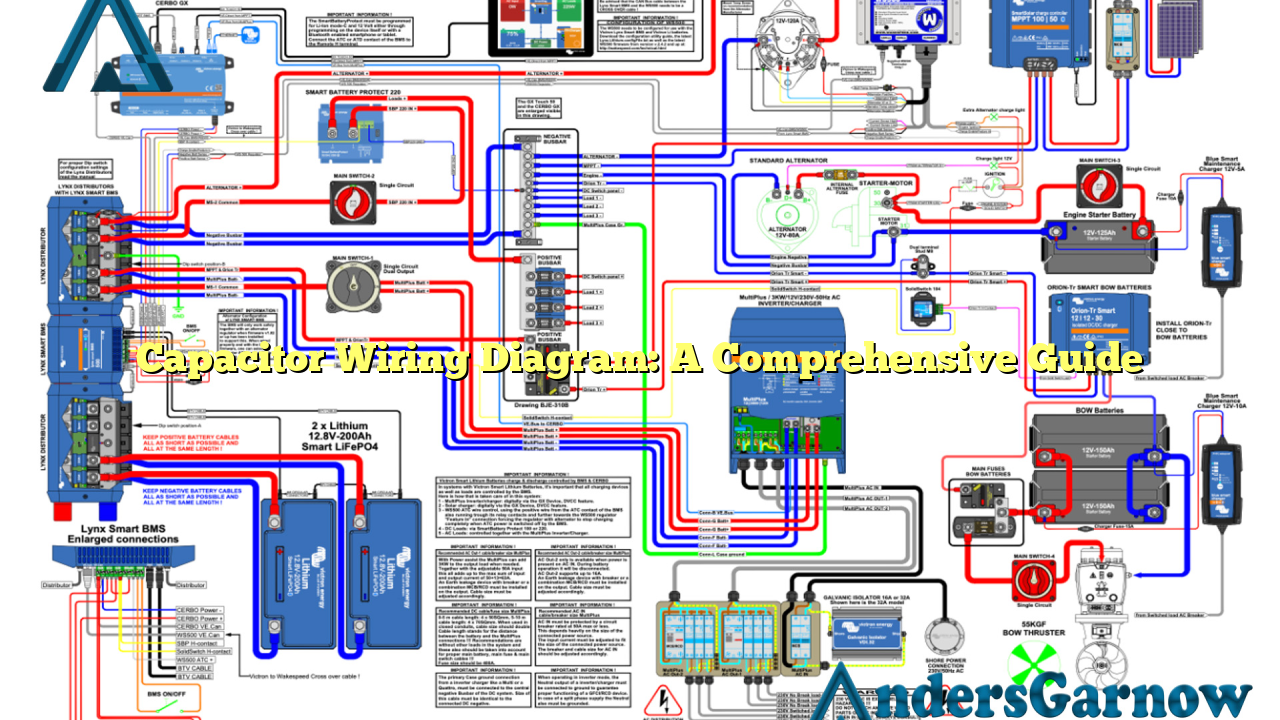
Capacitor wiring diagrams illustrate the connections between various terminals of a capacitor. These diagrams provide a visual representation of how to connect the capacitor in a circuit, ensuring proper functionality and preventing potential damage.
The wiring diagram typically includes labels for the positive and negative terminals, voltage ratings, and capacitance values. It also indicates the connection points with other components, such as resistors and power sources.
3. Advantages of Capacitor Wiring Diagrams
Capacitor wiring diagrams offer several advantages:
- Clear Visualization: The diagrams allow users to understand the connections easily, reducing the chances of errors during installation.
- Troubleshooting Aid: In case of any issues, the wiring diagram helps identify faulty connections or damaged components.
- Standardization: Wiring diagrams follow industry standards, ensuring compatibility and ease of use across different devices and applications.
4. Disadvantages of Capacitor Wiring Diagrams
Despite their usefulness, capacitor wiring diagrams also have some limitations:
- Complexity: Understanding and interpreting wiring diagrams may be challenging for individuals without a technical background.
- Space Limitations: In small devices or tight spaces, fitting the required connections as per the diagram can be difficult.
- Language Barrier: Some diagrams may use technical terms and symbols that are unfamiliar to non-experts.
5. Alternative Options for Capacitor Wiring
While capacitor wiring diagrams are widely used, alternative options exist for specific applications:
- Printed Circuit Board (PCB): In some cases, capacitors are integrated into PCB designs, eliminating the need for external wiring.
- Wire Harnesses: For complex systems with multiple capacitors, wire harnesses simplify the wiring process and ensure organized connections.
- Terminal Blocks: These blocks provide a convenient way to connect capacitors and other components, reducing wiring complexity.
6. Capacitor Wiring Diagram Table
| Terminal | Description |
|---|---|
| Positive (+) | Connects to the positive terminal of the power source |
| Negative (-) | Connects to the negative terminal of the power source |
| Voltage Rating | Specifies the maximum voltage the capacitor can handle |
| Capacitance | Indicates the capacity of the capacitor to store charge |
7. Frequently Asked Questions (FAQ)
Q: Can I use a higher voltage rating capacitor than specified in the wiring diagram?
A: It is not recommended to exceed the voltage rating mentioned in the wiring diagram as it may lead to capacitor failure or damage to other components.
Q: Can I connect multiple capacitors in parallel?
A: Yes, connecting capacitors in parallel increases the overall capacitance, providing a higher charge storage capacity.
Q: What happens if I reverse the polarity while wiring the capacitor?
A: Reversing the polarity can damage the capacitor and other components. Always ensure the correct connections as indicated in the wiring diagram.
Conclusion
Capacitor wiring diagrams play a vital role in ensuring proper installation and functionality of electrical circuits. While they have advantages in terms of visualization and troubleshooting, users should be aware of their limitations. Alternative options, such as PCB integration and wire harnesses, exist for specific scenarios. Understanding the wiring diagram and following industry standards are crucial for safe and efficient capacitor installations.

