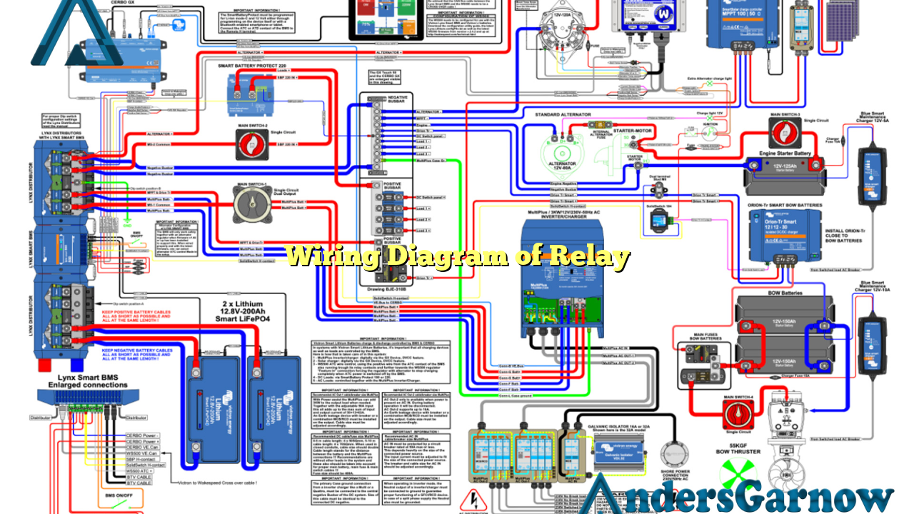
Hello readers! In this article, we will discuss the wiring diagram of a relay. A relay is an electrical device that allows a low-power signal to control a high-power circuit. It is commonly used in automotive, industrial, and residential applications. Understanding the wiring diagram of a relay is crucial for proper installation and troubleshooting. So, let’s dive into the details and learn how relays work and their various wiring configurations.
1. What is a Relay?
A relay is an electromechanical device that consists of a coil, an armature, a set of contacts, and a spring. When an electrical current flows through the coil, it generates a magnetic field that attracts the armature, causing the contacts to either open or close. The contacts act as a switch to control the flow of current in another circuit. Relays are used to control high-power devices with low-power signals, providing isolation and protection.
2. Types of Relays
There are various types of relays available, including electromagnetic relays, solid-state relays, thermal relays, and reed relays. Each type has its own advantages and applications. Electromagnetic relays are the most common type and are widely used due to their reliability and versatility.
3. Wiring Configuration
The wiring diagram of a relay shows the connections between the coil, contacts, and power sources. The coil is usually labeled as “C” or “Coil,” and it is connected to a power source with a control signal. The contacts are labeled as “NO” (Normally Open), “NC” (Normally Closed), and “COM” (Common). The NO contact is open when the relay is not energized, and it closes when the relay is energized. The NC contact is closed when the relay is not energized, and it opens when the relay is energized. The COM contact is common to both the NO and NC contacts.
4. Wiring Diagram Symbols
When reading a wiring diagram of a relay, it is essential to understand the symbols used. The coil is represented by a circle with a cross inside, while the contacts are represented by lines with different shapes. The NO contact is represented by a line that is not connected to anything, the NC contact is represented by a line connected to a diagonal line, and the COM contact is represented by a line connected to a horizontal line.
5. Advantages of Relays
Relays offer several advantages in electrical systems. Firstly, they provide electrical isolation between the control signal and the high-power circuit, protecting sensitive components. Secondly, relays can handle higher currents and voltages than most electronic components. Thirdly, relays allow for easy troubleshooting and replacement, as they can be easily swapped out without affecting the entire system. Lastly, relays are cost-effective compared to other control devices.
6. Disadvantages of Relays
Despite their advantages, relays also have some limitations. One major disadvantage is their mechanical nature, which means they have moving parts that can wear out over time. This can lead to reduced reliability and the need for regular maintenance. Additionally, relays consume more power compared to solid-state devices. They also produce electromagnetic interference (EMI) and can generate audible noise during operation.
7. Alternative Wiring Diagram
An alternative wiring diagram for relays is using a relay module. A relay module is a pre-packaged device that includes the relay, necessary components, and connectors. It simplifies the wiring process and reduces the chances of wiring errors. The module usually has screw terminals for easy connection and may include additional features like LED indicators for status indication. Using a relay module can save time and effort in complex wiring setups.
8. Wiring Diagram of Relay Table
| Contact | Description |
|---|---|
| NO (Normally Open) | Open when the relay is not energized, closes when energized |
| NC (Normally Closed) | Closed when the relay is not energized, opens when energized |
| COM (Common) | Common terminal connected to both NO and NC contacts |
9. Frequently Asked Questions (FAQ)
Q: Can I use a relay to control AC (alternating current) devices?
A: Yes, relays can be used to control both AC and DC devices. However, make sure to choose a relay that is rated for the specific voltage and current requirements of your application.
Q: How do I determine the coil voltage of a relay?
A: The coil voltage of a relay is typically specified by the manufacturer. It is important to select a relay with a coil voltage that matches the control signal voltage of your system.
Q: Can I use multiple relays together in a circuit?
A: Yes, multiple relays can be used together in a circuit. This allows for more complex control and switching operations.
Conclusion
In conclusion, understanding the wiring diagram of a relay is essential for proper installation and troubleshooting. Relays offer advantages such as electrical isolation, high-power handling, and easy replacement. However, they also have limitations like mechanical wear and power consumption. Using a relay module can simplify wiring setups. Remember to choose the appropriate relay type and follow the wiring diagram carefully to ensure safe and reliable operation in your electrical system.

