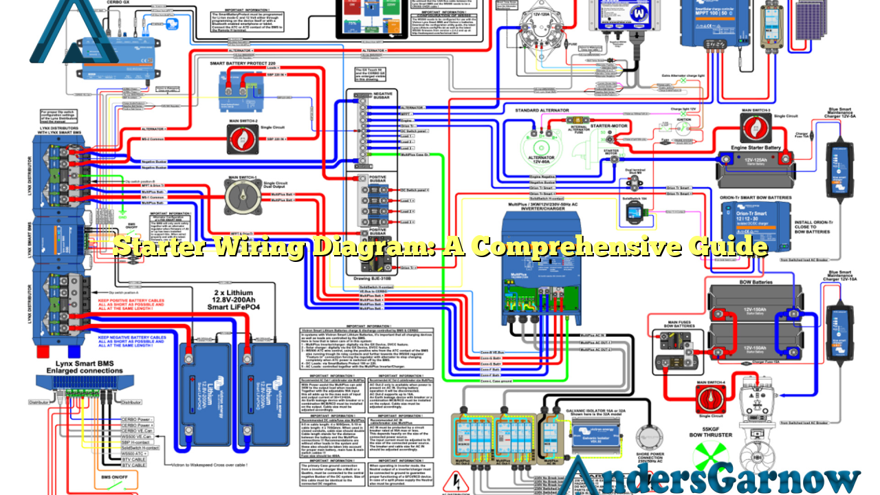
Hello readers! Today, we will delve into the world of starter wiring diagrams. If you are a DIY enthusiast or an automotive professional, understanding the intricacies of a starter wiring diagram is essential. In this article, we will explore the various aspects of a starter wiring diagram, its benefits, and potential alternatives. So, let’s get started!
1. What is a Starter Wiring Diagram?
A starter wiring diagram is a graphical representation of the electrical connections and components involved in the starting system of a vehicle. It provides a visual guide that helps in understanding how the starter motor, battery, ignition switch, and other related components are interconnected.
A typical starter wiring diagram consists of various symbols and lines that represent different electrical connections. By referring to the diagram, technicians can diagnose and troubleshoot any issues related to the starting system.
2. Benefits of Using a Starter Wiring Diagram
Using a starter wiring diagram offers several benefits, including:
- Easy Troubleshooting: When faced with a starting system problem, a wiring diagram helps identify the faulty component quickly.
- Accurate Repair: By following the diagram, technicians can ensure that the connections are made correctly during repairs or installations.
- Time-Saving: The diagram provides a clear overview, saving time that would otherwise be spent on trial and error.
- Enhanced Safety: Proper wiring prevents electrical mishaps and reduces the risk of short circuits or fires.
3. Understanding the Starter Wiring Diagram
In a starter wiring diagram, you will typically come across the following components:
- Battery: The power source that supplies electricity to the starting system.
- Starter Motor: The electric motor responsible for turning the engine’s crankshaft to start the vehicle.
- Ignition Switch: The switch that activates the starter motor when the key is turned.
- Solenoid: An electromagnetic switch that controls the flow of electricity from the battery to the starter motor.
- Fusible Link: A protective device that disconnects the circuit in case of excessive current flow.
- Relay: An electrically operated switch that controls a high-current circuit with a low-current signal.
- Ground Connections: Metal connections that provide a path for the electrical current to return to the battery.
4. Common Issues and Troubleshooting
While the starter wiring diagram helps diagnose problems, it is crucial to be aware of common issues that may arise. Some common problems include:
- Corroded Connections: Corrosion can interrupt the electrical flow, leading to starting issues. Regular maintenance and cleaning can prevent this problem.
- Weak Battery: A weak or discharged battery may not provide enough power to start the engine. Checking the battery’s health is essential.
- Faulty Starter Motor: If the motor fails to spin, it may indicate a problem with the starter motor itself. Testing the motor’s functionality is necessary.
- Defective Ignition Switch: A faulty ignition switch can prevent the starter motor from receiving power. Replacing the switch may be required.
When troubleshooting, ensure that you have a proper understanding of the starter wiring diagram to identify the root cause accurately.
5. Alternatives to Starter Wiring Diagrams
While starter wiring diagrams provide a comprehensive understanding, alternative methods can also be used:
- Repair Manuals: Vehicle-specific repair manuals often include step-by-step instructions and diagrams for various systems, including the starting system.
- Online Forums and Communities: Engaging with automotive enthusiasts and professionals through online platforms can provide valuable insights and alternative solutions.
- Video Tutorials: Video tutorials on platforms like YouTube can visually guide you through the process of troubleshooting and repairing the starting system.
6. Starter Wiring Diagram: Detailed Information
| Component | Description |
|---|---|
| Battery | The power source that supplies electrical energy to the starting system. |
| Starter Motor | An electric motor that turns the engine’s crankshaft to initiate the starting process. |
| Ignition Switch | A switch that activates the starter motor by completing the circuit. |
| Solenoid | An electromagnetic switch that controls the flow of electricity from the battery to the starter motor. |
| Fusible Link | A protective device that disconnects the circuit in case of excessive current flow. |
| Relay | An electrically operated switch that controls a high-current circuit with a low-current signal. |
| Ground Connections | Metal connections that provide a path for the electrical current to return to the battery. |
7. Frequently Asked Questions (FAQ)
Q: Can I use a starter wiring diagram for any vehicle?
A: Starter wiring diagrams are vehicle-specific. It is essential to refer to the specific diagram for your vehicle’s make, model, and year to ensure accurate connections.
Q: How do I interpret the symbols in a starter wiring diagram?
A: The symbols in a starter wiring diagram represent various electrical components. Referring to the diagram’s legend or key will help you understand the meaning of each symbol.
Q: Can I replace a starter motor without referring to a wiring diagram?
A: While it is possible to replace a starter motor without a wiring diagram, referring to the diagram ensures that the connections are made correctly, minimizing the risk of damage or malfunction.
In Conclusion
In conclusion, a starter wiring diagram serves as a valuable tool for understanding and troubleshooting the starting system of a vehicle. By referring to the diagram, individuals can accurately identify and resolve any issues that may arise. Remember to use accurate vehicle-specific diagrams and follow safety precautions while working on the electrical system. With the knowledge gained from this article, you are now equipped to tackle starter wiring diagrams with confidence!

