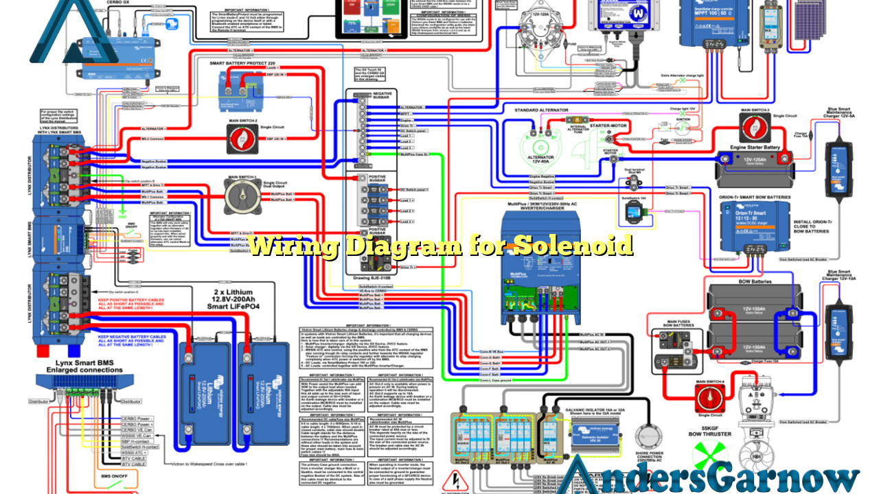
Hello and welcome to our comprehensive guide on wiring diagrams for solenoids. In this article, we will provide you with detailed information on how to properly wire a solenoid, including its advantages, disadvantages, and alternative wiring options. So, let’s dive right in!
1. Understanding Solenoids
Before we delve into the wiring diagram, it’s essential to understand what a solenoid is and its purpose. A solenoid is an electromagnetic device that converts electrical energy into linear motion. It typically consists of a coil, a core, and a plunger. Solenoids are widely used in various applications, including automotive systems, industrial machinery, and home appliances.
2. Wiring Diagram for Solenoid
When it comes to wiring a solenoid, it’s crucial to follow a specific diagram to ensure proper functionality. The most common wiring diagram for a solenoid involves connecting the positive terminal of the power source to one side of the coil and the negative terminal to the other side. The load is then connected to the moving plunger or the movable contact of the solenoid.
Advantages of Properly Wired Solenoids
Proper wiring of solenoids offers several advantages:
- Efficient Energy Conversion: A correctly wired solenoid ensures optimal energy conversion, resulting in improved performance and reduced power consumption.
- Reliable Operation: Following the correct wiring diagram enhances the solenoid’s reliability, reducing the risk of malfunction or failure.
- Easy Troubleshooting: If any issues arise, a well-documented wiring diagram simplifies the troubleshooting process, saving time and effort.
Disadvantages of Improper Wiring
On the other hand, improper wiring of solenoids can lead to various issues:
- Malfunctioning: Incorrect wiring may cause the solenoid to operate erratically or not function at all.
- Electrical Damage: Inadequate wiring can result in electrical damage to the solenoid or other connected components.
- Safety Hazards: Faulty wiring increases the risk of electrical shocks or fires, posing safety hazards.
3. Alternative Wiring Options
While the standard wiring diagram for solenoids is widely used, there are alternative options available based on specific requirements. Some alternatives include:
- Parallel Wiring: In certain cases, parallel wiring may be preferred, where multiple solenoids are connected in parallel to achieve higher current carrying capacity.
- Series Wiring: Series wiring is another alternative, suitable for applications where solenoids need to share the current flow.
4. Wiring Diagram for Solenoid – Detailed Breakdown
For a more detailed understanding, refer to the following table that provides a comprehensive breakdown of the wiring diagram for solenoids:
| Terminal/Component | Connection |
|---|---|
| Positive Terminal of Power Source | Connected to one side of the coil |
| Negative Terminal of Power Source | Connected to the other side of the coil |
| Load | Connected to the moving plunger or movable contact of the solenoid |
5. Frequently Asked Questions (FAQ)
Q: Can I reverse the polarity in the solenoid wiring diagram?
A: It is not recommended to reverse the polarity in the solenoid wiring diagram as it may lead to malfunctioning or damage of the solenoid.
Q: Can I use a different power source voltage for the solenoid?
A: It is crucial to use the recommended power source voltage specified by the solenoid manufacturer to ensure safe and proper operation.
Conclusion
In conclusion, properly wiring a solenoid is essential to ensure its optimal performance, reliability, and safety. By following the correct wiring diagram, you can avoid potential issues and enjoy the advantages of efficient energy conversion and easy troubleshooting. Remember to adhere to the recommended wiring guidelines provided by the solenoid manufacturer and consult a professional if needed. Happy wiring!

