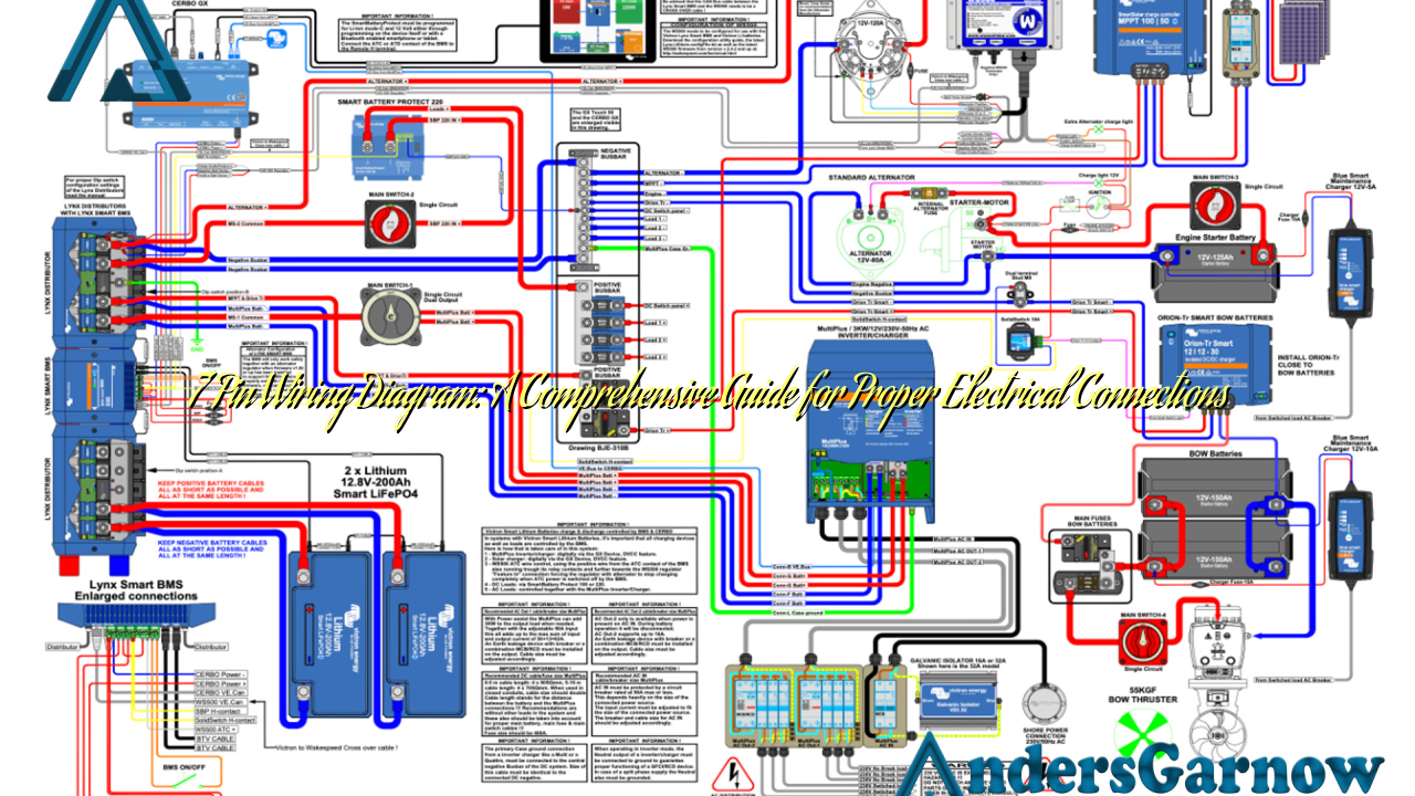
Hello readers! Today, we will delve into the world of 7 pin wiring diagrams, an essential aspect of electrical connections in various applications. Whether you are a seasoned electrician or a DIY enthusiast, understanding the intricacies of a 7 pin wiring diagram is crucial for successful installations. In this article, we will explore 10 subtopics related to 7 pin wiring diagrams, discussing their features, advantages, disadvantages, and alternative options. So, let’s dive in!
1. Understanding the Basics of a 7 Pin Wiring Diagram
A 7 pin wiring diagram is a visual representation of the electrical connections required for a specific application. It typically consists of seven pins, each serving a distinct purpose. These pins are labeled and color-coded to ensure proper identification and connection.
Advantages:
- Clear visual guide for proper wiring
- Standardized connections for compatibility
- Easy identification of pin functions
Disadvantages:
- Requires prior knowledge of electrical systems
- May vary slightly depending on the application
- Improper wiring can lead to malfunctions or accidents
2. Pin-by-Pin Breakdown and Functions
In this section, we will explore each pin’s function in a 7 pin wiring diagram. Understanding these pins is crucial for proper installation and troubleshooting.
| Pin Number | Color | Function |
|---|---|---|
| 1 | Yellow | Left Turn and Brake Lights |
| 2 | Blue | Reverse Lights |
| 3 | White | Ground |
| 4 | Green | Right Turn and Brake Lights |
| 5 | Brown | Tail and Marker Lights |
| 6 | Red | Brake Control |
| 7 | Black | Battery Charge (+12V) |
3. Benefits of Using a 7 Pin Wiring Diagram
When it comes to electrical connections, using a 7 pin wiring diagram offers several advantages:
- Ensures proper and standardized connections
- Reduces the risk of wiring errors
- Facilitates compatibility between different systems
- Simplifies troubleshooting and repairs
4. Common Issues and Troubleshooting
Despite their reliability, 7 pin wiring diagrams may encounter certain issues. Here are a few common problems and their solutions:
- No power in certain pins: Check the connections and ensure proper grounding.
- Flickering lights: Inspect the wiring for any loose connections or damaged wires.
- Intermittent functionality: Verify the integrity of the pins and connectors.
5. Alternative Wiring Options
While the 7 pin wiring diagram is widely used, there are alternative options available for specific applications. Some alternatives include:
- 4 pin wiring diagrams
- 5 pin wiring diagrams
- 6 pin wiring diagrams
Each alternative has its own pin configuration and is suitable for different purposes.
6. Frequently Asked Questions (FAQ)
Q: Can I use a 7 pin wiring diagram for my trailer?
A: Yes, a 7 pin wiring diagram is commonly used for trailers. It provides the necessary connections for various lights and brakes.
Q: Are there universal color codes for the pins?
A: While there are standardized color codes, it is essential to refer to the specific diagram or documentation to ensure accurate connections.
Q: Can I extend the wires in a 7 pin wiring diagram?
A: Yes, it is possible to extend the wires; however, proper insulation and secure connections are crucial to avoid signal loss or electrical faults.
Conclusion
In conclusion, a 7 pin wiring diagram is a vital tool for anyone involved in electrical installations. It provides a clear understanding of the connections required for various applications, ensuring proper functionality and safety. While it may have its complexities, the advantages of using a 7 pin wiring diagram outweigh the disadvantages. By following the pin functions, troubleshooting techniques, and considering alternative options, you can confidently tackle any electrical project requiring a 7 pin wiring diagram. Happy wiring!

