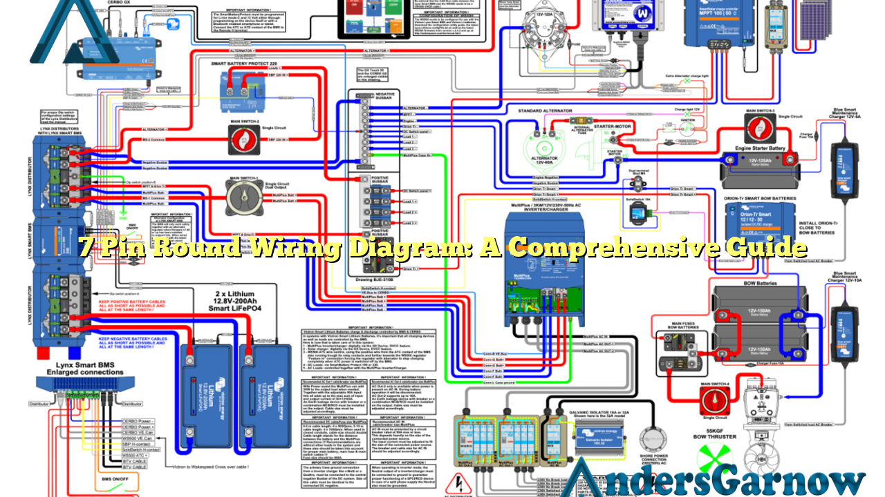
Hello readers! In today’s article, we will delve into the fascinating world of 7 pin round wiring diagrams. Whether you are a seasoned electrician or a novice DIY enthusiast, this comprehensive guide will provide you with all the information you need to understand and utilize this wiring diagram effectively. So, let’s dive in!
1. What is a 7 Pin Round Wiring Diagram?
A 7 pin round wiring diagram is a visual representation of the electrical connections and functions of a round connector commonly used for towing trailers and caravans. It illustrates the various pins, their wire colors, and the corresponding functions, making it easier to connect the towing vehicle to the trailer.
Advantages:
- Provides a standardized and universal wiring solution for trailers
- Ensures proper and secure electrical connections
- Allows for the transmission of important signals, such as turn signals, brake lights, and taillights
- Enables the use of additional accessories, like electric brakes and reverse lights
Disadvantages:
- Requires knowledge and understanding of electrical systems
- Can be confusing for beginners
- May require additional tools and equipment for installation
2. Pin Configuration
The 7 pin round connector consists of seven pins, each with a specific function. Here is a breakdown of the pin configuration:
| Pin | Wire Color | Function |
|---|---|---|
| 1 | Black | Charge |
| 2 | Blue | Electric Brakes |
| 3 | Brown | Tail, License, and Side Marker Lights |
| 4 | Red | Stop and Turn Lights |
| 5 | Green | Right Turn Signal and Brake |
| 6 | Yellow | Left Turn Signal and Brake |
| 7 | White | Ground |
3. Wiring Instructions
To connect the towing vehicle to the trailer, follow these wiring instructions:
- Charge (Pin 1): Connect the black wire to the vehicle’s positive battery terminal to charge the trailer’s battery while driving.
- Electric Brakes (Pin 2): Connect the blue wire to the electric brake controller in the towing vehicle to activate the trailer’s electric brakes.
- Tail, License, and Side Marker Lights (Pin 3): Connect the brown wire to the respective lights on the trailer to illuminate them.
- Stop and Turn Lights (Pin 4): Connect the red wire to the trailer’s stop and turn lights for proper functionality.
- Right Turn Signal and Brake (Pin 5): Connect the green wire to the right turn signal and brake lights on the trailer.
- Left Turn Signal and Brake (Pin 6): Connect the yellow wire to the left turn signal and brake lights on the trailer.
- Ground (Pin 7): Connect the white wire to the vehicle’s chassis or a suitable ground point to ensure a proper ground connection.
4. Alternative Wiring Diagram
Although the 7 pin round wiring diagram is widely used, there is an alternative wiring configuration known as the 7 pin flat wiring diagram. In this configuration, the pins are arranged in a flat layout instead of a round connector. The pin functions remain the same, but the wiring color codes may vary.
5. Frequently Asked Questions (FAQ)
Q: Can I use a 7 pin round wiring diagram for a 5 pin connector?
A: No, a 7 pin round wiring diagram is specifically designed for a 7 pin connector. Using it for a 5 pin connector may result in improper connections and functionality.
Q: Are there adapters available for different wiring configurations?
A: Yes, there are adapters available that allow you to connect different wiring configurations. However, it is crucial to ensure compatibility between the towing vehicle and the trailer.
Q: Can I install a 7 pin round connector myself?
A: If you have experience and knowledge of electrical systems, you can install a 7 pin round connector yourself. However, it is recommended to consult a professional if you are unsure.
Conclusion
In conclusion, a 7 pin round wiring diagram is an essential tool for anyone towing trailers or caravans. It provides a standardized and reliable method for connecting the towing vehicle to the trailer, ensuring the proper functioning of essential signals and accessories. By understanding the pin configuration and following the wiring instructions, you can confidently install and utilize this wiring diagram for your towing needs.

