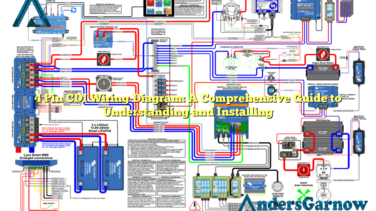
Hello readers, welcome to our informative article on the 4 pin CDI wiring diagram. In this guide, we will provide you with a detailed explanation of the wiring diagram, its components, installation process, as well as the advantages and disadvantages of using a 4 pin CDI system. So, let’s dive right in!
1. Introduction to 4 Pin CDI Wiring Diagram
The 4 pin CDI (Capacitor Discharge Ignition) system is a crucial component in the ignition system of a motorcycle or any other small engine. It is responsible for generating the high voltage required to ignite the spark plug, which in turn ignites the fuel-air mixture in the combustion chamber. The wiring diagram illustrates the connections between the CDI unit, ignition coil, stator, and other electrical components.
2. Components of a 4 Pin CDI Wiring Diagram
A standard 4 pin CDI wiring diagram consists of the following components:
| Pin Number | Component |
|---|---|
| 1 | Pulse Generator |
| 2 | Ignition Coil |
| 3 | CDI Unit |
| 4 | Ground |
Each component plays a crucial role in ensuring proper ignition and smooth engine operation.
3. Wiring Connections and Color Codes
Understanding the wiring connections and color codes is essential for a successful installation of the 4 pin CDI system. The CDI unit should be connected to the pulse generator, ignition coil, and ground following the specific color codes provided by the manufacturer.
4. Advantages of Using a 4 Pin CDI Wiring Diagram
The 4 pin CDI system offers several advantages:
- Enhanced Ignition Timing: The CDI system allows for precise ignition timing, resulting in improved engine performance.
- Reliability: Compared to traditional contact breaker points, CDI systems are more reliable and require less maintenance.
- Increased Fuel Efficiency: Proper ignition timing ensures efficient combustion, leading to better fuel efficiency.
- Easy Installation: With a clear wiring diagram and proper instructions, installing a 4 pin CDI system can be relatively simple.
5. Disadvantages of Using a 4 Pin CDI Wiring Diagram
While the 4 pin CDI system offers several advantages, it also has some drawbacks:
- Cost: CDI systems can be more expensive compared to traditional ignition systems.
- Compatibility Issues: Not all engines are compatible with a 4 pin CDI system, requiring modifications or alternative solutions.
- Complexity: Understanding the wiring connections and troubleshooting any issues can be challenging for beginners.
6. Alternative to 4 Pin CDI Wiring Diagram
If your engine is not compatible with a 4 pin CDI system, there are alternative solutions available. One option is to use a 5 pin CDI system, which offers additional features such as a built-in rev limiter or an advanced timing curve. However, it is crucial to ensure compatibility and understand the specific wiring connections for the alternative system.
7. Frequently Asked Questions (FAQ)
Q: Can I install a 4 pin CDI system on any motorcycle?
A: Not all motorcycles are compatible with a 4 pin CDI system. It is essential to check your engine specifications and consult with a professional to determine compatibility.
Q: How can I troubleshoot issues with my 4 pin CDI system?
A: Start by checking the wiring connections and ensuring they are correct. If the connections are fine, you might need to test the individual components or seek assistance from a mechanic.
Conclusion
In conclusion, the 4 pin CDI wiring diagram provides a comprehensive understanding of the ignition system. It offers advantages such as enhanced ignition timing and reliability, but it also has drawbacks like cost and compatibility issues. It is crucial to follow the wiring connections and color codes accurately during installation. If your engine is not compatible, alternative solutions like a 5 pin CDI system can be considered. Remember to consult professionals and refer to the manufacturer’s instructions for a successful installation and troubleshooting process.

