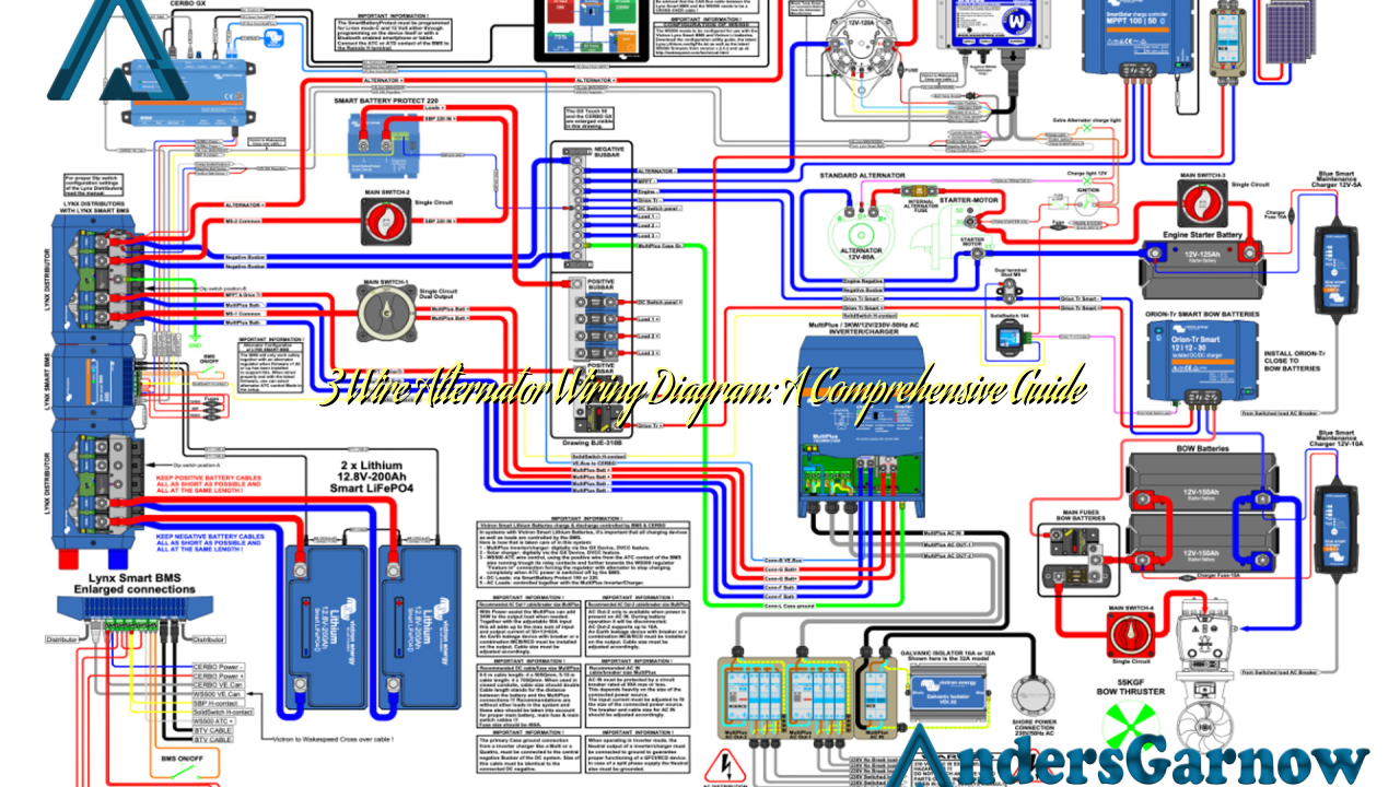
Hello, dear readers! Are you in search of a reliable and efficient wiring diagram for your 3 wire alternator? Well, you have come to the right place. In this article, we will provide you with a detailed guide on 3 wire alternator wiring diagrams and explore their advantages, disadvantages, and alternative options. So, let’s dive into the world of alternator wiring!
1. Understanding the Basics of a 3 Wire Alternator Wiring Diagram
Before we delve into the intricacies of a 3 wire alternator wiring diagram, let’s first understand its basic components. A 3 wire alternator consists of three main connections: the battery positive terminal, the voltage sensing wire, and the ignition input wire. These connections play a crucial role in ensuring the efficient functioning of the alternator.
The battery positive terminal is responsible for providing power to the alternator, which it converts into electrical energy. The voltage sensing wire, on the other hand, is connected to the battery’s positive terminal and allows the alternator to sense the battery voltage. Finally, the ignition input wire is connected to the ignition switch and regulates the alternator’s output based on the demands of the electrical system.
2. Advantages of a 3 Wire Alternator Wiring Diagram
Using a 3 wire alternator wiring diagram offers several advantages over other wiring options. Firstly, it simplifies the wiring process by eliminating the need for additional components like external voltage regulators. This makes installation easier and reduces the chances of wiring errors.
Secondly, a 3 wire alternator wiring diagram ensures a more stable voltage output. The voltage sensing wire allows the alternator to detect the battery’s voltage, enabling it to adjust its output accordingly. This feature prevents overcharging or undercharging of the battery, prolonging its lifespan and ensuring optimal performance.
3. Disadvantages of a 3 Wire Alternator Wiring Diagram
While a 3 wire alternator wiring diagram offers numerous benefits, it also has a few limitations. One disadvantage is that it may not be compatible with all vehicle models. Some vehicles require specific wiring configurations, and using a 3 wire alternator wiring diagram may not be suitable in such cases.
Another drawback is that the voltage sensing wire can cause a voltage drop, especially in vehicles with extensive wiring. This drop in voltage can lead to a decrease in electrical system performance and may require additional measures to compensate for the loss.
4. Alternative Wiring Options
If a 3 wire alternator wiring diagram is not suitable for your vehicle, there are alternative options available. One popular alternative is a 1 wire alternator system. In this setup, the alternator is wired directly to the battery, eliminating the need for a voltage sensing wire. While it offers simplicity, it may not provide the same level of voltage regulation as a 3 wire system.
Another alternative is a 2 wire alternator system, which includes a battery sensing wire in addition to the primary wire. This setup provides better voltage regulation compared to a 1 wire system but may require additional wiring modifications.
5. 3 Wire Alternator Wiring Diagram: Complete Guide
| Connection | Description |
|---|---|
| Battery positive terminal | Connects to the alternator to provide power |
| Voltage sensing wire | Connected to the battery’s positive terminal, allows the alternator to sense battery voltage |
| Ignition input wire | Connected to the ignition switch, regulates alternator output based on electrical system demands |
The 3 wire alternator wiring diagram involves connecting the battery positive terminal to the alternator’s output post. The voltage sensing wire is then connected to the battery’s positive terminal, and the ignition input wire is connected to the ignition switch. This wiring configuration ensures a smooth flow of power and efficient voltage regulation.
6. Frequently Asked Questions (FAQ) – 3 Wire Alternator Wiring Diagram
Q: Can I use a 3 wire alternator wiring diagram for any vehicle?
A: While a 3 wire alternator wiring diagram is suitable for many vehicles, it may not be compatible with all models. It’s essential to consult your vehicle’s manual or a professional to determine the appropriate wiring diagram for your specific vehicle.
Q: What is the purpose of the voltage sensing wire?
A: The voltage sensing wire allows the alternator to sense the battery’s voltage and regulate its output accordingly. This feature ensures optimal charging of the battery and prevents overcharging or undercharging.
In Conclusion
In conclusion, a 3 wire alternator wiring diagram offers a reliable and efficient solution for your vehicle’s electrical system. It simplifies the wiring process, provides stable voltage output, and ensures optimal battery performance. However, it may not be compatible with all vehicles, and there are alternative options available, such as 1 wire or 2 wire systems. Regardless of the wiring option you choose, it’s crucial to follow the appropriate wiring diagram and seek professional assistance if needed. Happy wiring!

