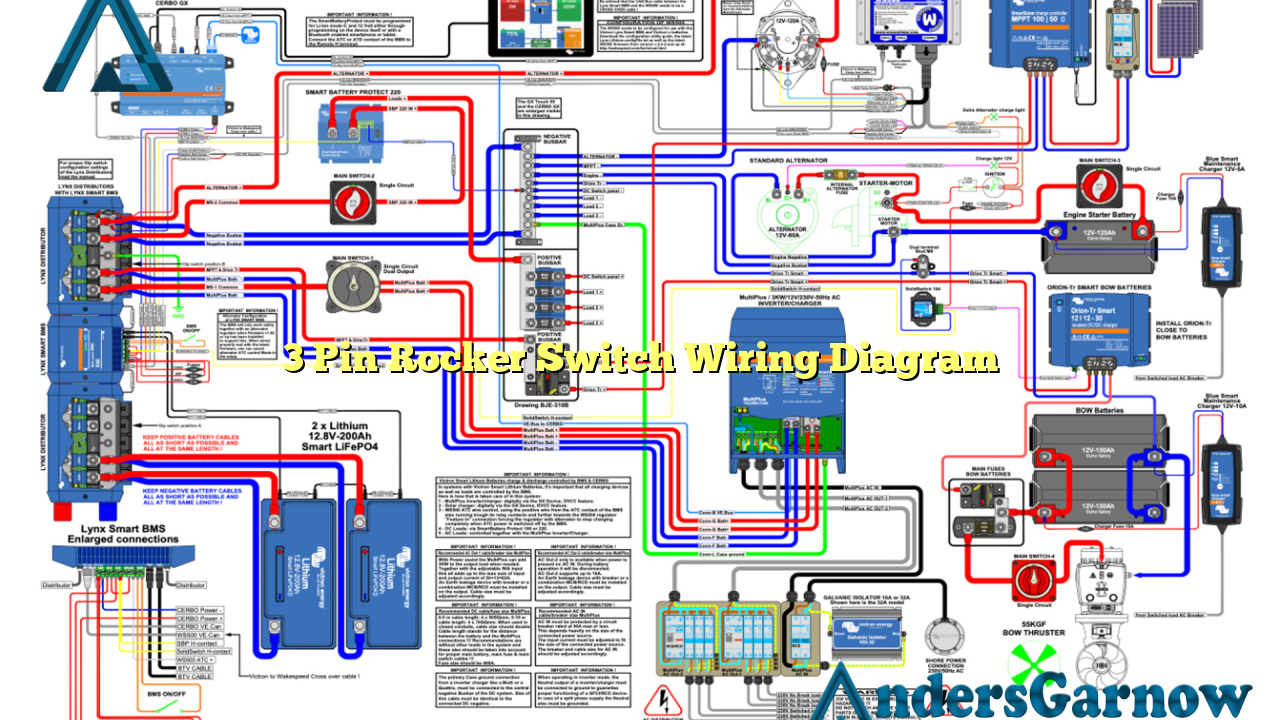
Hello readers, welcome to our informative article about the 3 pin rocker switch wiring diagram. In this article, we will discuss the various aspects of this wiring diagram, its advantages and disadvantages, alternative options, and provide a detailed explanation of each subtopic. So, let’s dive in!
1. Understanding the Basics of a 3 Pin Rocker Switch Wiring Diagram
Before we proceed, let’s have a brief overview of what a 3 pin rocker switch is and how it works. A 3 pin rocker switch is a type of electrical switch that can be used to control the flow of current in a circuit. It consists of three pins – the input pin, the output pin, and the ground pin. The wiring diagram illustrates how these pins are connected to the electrical components in a circuit.
2. Pin Configuration and Wiring
The wiring diagram clearly shows the pin configuration of a 3 pin rocker switch. The input pin is connected to the power source, the output pin is connected to the load, and the ground pin is connected to the ground or neutral wire. It is essential to follow the correct wiring configuration to ensure proper functioning of the switch.
3. Advantages of Using a 3 Pin Rocker Switch
There are several advantages of using a 3 pin rocker switch in electrical circuits. Firstly, it provides a convenient and easy way to control the flow of current. Secondly, it offers a visually appealing design with its rocker-style switch. Additionally, it is durable and long-lasting, making it suitable for various applications.
4. Disadvantages of Using a 3 Pin Rocker Switch
While there are advantages, it is important to consider the disadvantages as well. One of the drawbacks is that it requires proper wiring and installation for optimal performance. Another disadvantage is that it may not be suitable for high voltage applications. Care must also be taken to ensure the switch is rated for the desired current and voltage.
5. Detailed Explanation of Wiring Steps
Now, let’s take a closer look at the wiring steps involved in connecting a 3 pin rocker switch. Firstly, identify the input, output, and ground pins on the switch. Then, connect the input pin to the power source using a wire. Next, connect the output pin to the load that you want to control. Finally, connect the ground pin to the ground or neutral wire. Double-check the connections to ensure they are secure and properly insulated.
6. Alternative Options
If a 3 pin rocker switch is not suitable for your specific application, there are alternative options available. One popular alternative is the toggle switch, which operates by flipping a lever up or down to control the current flow. Another option is the push-button switch, which is pressed to turn the circuit on or off. Consider your requirements and choose the switch that best fits your needs.
7. Complete Wiring Diagram Table
| Pin | Description |
|---|---|
| Input | Connected to the power source |
| Output | Connected to the load |
| Ground | Connected to the ground or neutral wire |
8. Frequently Asked Questions (FAQ)
Q: Can I use a 3 pin rocker switch for high voltage applications?
A: It is recommended to check the specifications of the switch to ensure it is rated for the desired voltage. If not, consider using a switch specifically designed for high voltage applications.
Q: Can I connect multiple loads to a single 3 pin rocker switch?
A: Yes, you can connect multiple loads in parallel, but ensure that the total current does not exceed the switch’s rating.
Conclusion
In conclusion, the 3 pin rocker switch wiring diagram provides a clear understanding of how to connect this type of switch in electrical circuits. It offers several advantages such as easy control of current flow and a visually appealing design. However, proper wiring and consideration of its limitations are essential. If a 3 pin rocker switch is not suitable, alternative options like toggle switches or push-button switches can be considered. Always refer to the switch’s specifications and follow the correct wiring steps for safe and efficient operation. Thank you for reading!

