Hello and welcome to our article on 3 phase contactor wiring diagram start stop PDF. In this article, we will provide you with detailed information on how to wire a 3 phase contactor for starting and stopping electrical motors. Understanding the wiring diagram is crucial for ensuring the proper functioning of the contactor. So, let’s dive in and explore this topic further.
1. What is a Contactor?
A contactor is an electrical device used to control the flow of electricity in an electrical circuit. It is commonly used to start, stop, and reverse the direction of motors. The 3 phase contactor is specifically designed for three-phase electrical systems, where three hot wires supply power to the motor.
2. Wiring Diagram Basics
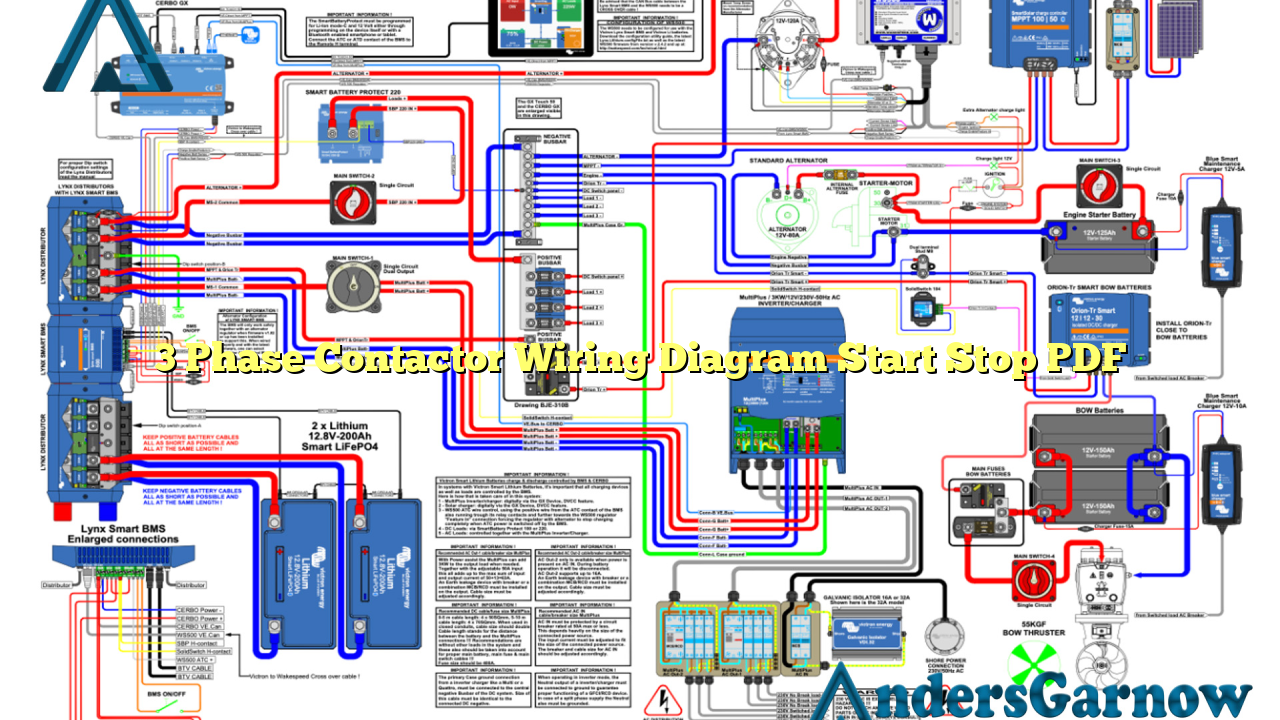
A wiring diagram is a visual representation of the electrical connections and functions of a specific circuit. In the case of a 3 phase contactor wiring diagram start stop PDF, it provides a clear illustration of how to connect the contactor, motor, and other components in the circuit.
The diagram typically includes symbols that represent the contactor, motor, power supply, start button, stop button, and other relevant elements. Following the wiring diagram ensures the correct installation and operation of the contactor.
3. Wiring the Contactor
Before starting the wiring process, it is essential to understand the contactor’s terminals and their functions. The contactor usually has three main terminals labeled L1, L2, and L3 for the three-phase power supply. It also has auxiliary contacts labeled A1 and A2 for control purposes.
To wire the contactor, follow these steps:
- Connect the power supply wires to the L1, L2, and L3 terminals.
- Connect the motor wires to the contactor terminals labeled T1, T2, and T3.
- Connect the control circuit wires to the auxiliary contacts A1 and A2.
It is crucial to ensure that the wiring is done according to the wiring diagram to avoid any electrical hazards or malfunctions.
4. Starting the Motor
To start the motor using the contactor, follow these steps:
- Press the start button to energize the coil of the contactor.
- The contactor’s coil creates a magnetic field, which pulls the contacts together, allowing the current to flow through the motor.
- The motor starts running and continues to run as long as the start button is pressed.
5. Stopping the Motor
To stop the motor using the contactor, follow these steps:
- Press the stop button to de-energize the coil of the contactor.
- The magnetic field in the coil collapses, and the contacts of the contactor open, interrupting the current flow to the motor.
- The motor comes to a stop.
6. Advantages of 3 Phase Contactor Wiring Diagram Start Stop PDF
The advantages of using a wiring diagram for the 3 phase contactor start stop circuit are:
- Clear understanding: The wiring diagram provides a clear visual representation of the connections, making it easier to understand and follow during installation.
- Accuracy: Following the wiring diagram ensures accurate wiring connections, reducing the chances of errors or malfunctions.
- Troubleshooting: In case of any issues, the wiring diagram serves as a reference point for troubleshooting and identifying potential problems.
7. Limitations of 3 Phase Contactor Wiring Diagram Start Stop PDF
While the wiring diagram is a useful tool, it has some limitations:
- Complexity: Wiring diagrams can be complex, especially for individuals with limited electrical knowledge. It may require professional assistance in some cases.
- Specificity: The wiring diagram is specific to the particular motor and contactor model. Different models may have slight variations in their wiring configurations.
- Updates: If any changes or modifications are made to the circuit, the wiring diagram needs to be updated accordingly to reflect the new connections.
8. Alternative Wiring Methods
There are alternative wiring methods for the 3 phase contactor start stop circuit, such as using a motor starter or a programmable logic controller (PLC). These alternatives provide additional functionalities and control options for the motor.
9. 3 Phase Contactor Wiring Diagram Start Stop PDF – Complete Information
| Component | Terminal | Description |
|---|---|---|
| Contactors | L1, L2, L3 | Connect to the three-phase power supply |
| Motor | T1, T2, T3 | Connect to the motor’s power terminals |
| Control Circuit | A1, A2 | Connect to the start and stop buttons or other control devices |
10. Frequently Asked Questions (FAQ)
Q: Can I use a single-phase contactor for a three-phase motor?
A: No, a single-phase contactor is designed for single-phase motors. You need to use a three-phase contactor for a three-phase motor.
Q: What is the purpose of the auxiliary contacts?
A: The auxiliary contacts are used for control purposes. They can be connected to other devices, such as control relays or indicator lights, to provide additional functionalities.
Q: Can I use the same contactor for both starting and stopping the motor?
A: Yes, the same contactor can be used for both starting and stopping the motor. The start and stop buttons control the energization and de-energization of the contactor’s coil.
Conclusion
In conclusion, understanding the 3 phase contactor wiring diagram start stop PDF is essential for proper installation and operation of the contactor. Following the wiring diagram ensures accurate connections and reduces the chances of electrical hazards. While the diagram has its limitations, it provides a clear understanding of the circuit’s configuration. Additionally, alternative wiring methods and the FAQ section provide further insights into this topic. Always refer to the specific wiring diagram provided by the manufacturer for your motor and contactor model.

