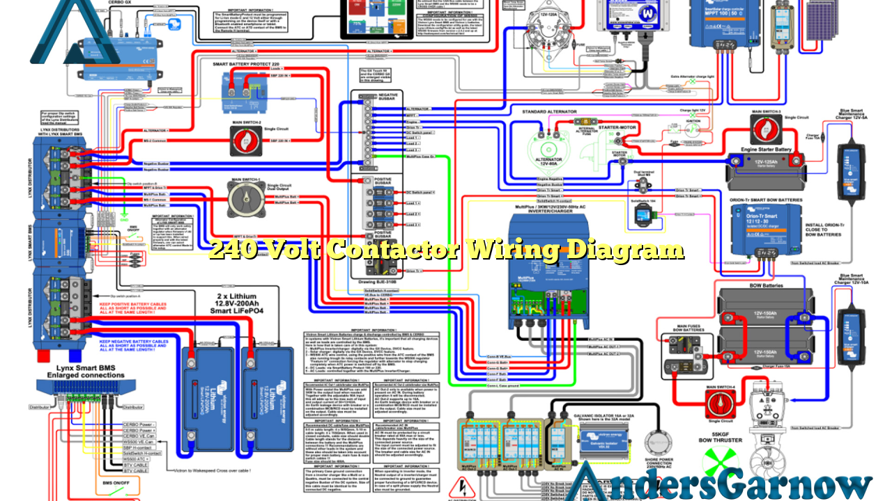
Hello, dear readers! Today, we will delve into the world of electrical wiring and explore the intricacies of a 240 volt contactor wiring diagram. This comprehensive guide will provide you with detailed information on how to properly wire a 240 volt contactor, its advantages and disadvantages, alternative options, and a helpful FAQ section. So, let’s get started!
1. Understanding the Basics of a 240 Volt Contactor Wiring Diagram
A 240 volt contactor is an electrical device used to control the flow of electricity to various components in a circuit. It consists of a coil, contacts, and a housing. The contactor’s primary function is to switch the electrical power supply on or off, allowing the circuit to function or remain idle.
When it comes to wiring a 240 volt contactor, it is crucial to understand the different terminals and connections involved. The wiring diagram provides a visual representation of how the contactor should be wired, ensuring correct and safe installation.
2. Advantages of Using a 240 Volt Contactor
There are several advantages to using a 240 volt contactor in electrical circuits:
- Reliable Control: A contactor offers a reliable way to control electrical power, ensuring smooth operation of the connected equipment.
- Enhanced Safety: By using a contactor, you can isolate the circuit from the power supply when necessary, preventing accidents and electrical hazards.
- Remote Control: Some contactors come with additional features, such as remote control capabilities, allowing you to conveniently operate the circuit from a distance.
- Longevity: Contactors are built to handle high electrical loads, making them durable and long-lasting.
3. Disadvantages of Using a 240 Volt Contactor
While there are numerous advantages, it is essential to consider the potential disadvantages of using a 240 volt contactor:
- Cost: Contactors can be more expensive compared to alternative solutions, especially for smaller-scale applications.
- Complexity: Wiring a contactor requires some knowledge of electrical systems, and incorrect installation can lead to malfunctions or safety risks.
- Space Requirements: Contactors typically require additional space in electrical enclosures due to their physical size.
4. Alternative Wiring Options for Controlling Electrical Power
If a 240 volt contactor does not suit your needs, there are alternative wiring options available:
- Manual Switches: Manual switches provide a simple way to control electrical power, but they lack the convenience and automation of a contactor.
- Relays: Relays function similarly to contactors but are often used in lower voltage applications. They are suitable alternatives when dealing with smaller electrical loads.
- Electronic Switches: Electronic switches offer advanced control options and can be programmed to automate various electrical processes.
5. 240 Volt Contactor Wiring Diagram – Step by Step Guide
To wire a 240 volt contactor correctly, follow these steps:
- Turn off the power supply to the circuit you are working on.
- Identify the contactor’s terminals and their respective functions (e.g., power in, power out, control coil).
- Connect the power supply wires to the appropriate terminals, ensuring proper sizing and tight connections.
- Wire the control coil according to the manufacturer’s instructions, typically using low voltage control wires.
- Double-check all connections and ensure that no bare wires are exposed.
- Turn on the power supply and test the contactor’s functionality.
6. Frequently Asked Questions (FAQ) – 240 Volt Contactor Wiring Diagram
| Question | Answer |
|---|---|
| Can I wire a 240 volt contactor with smaller gauge wires? | No, it is crucial to use properly sized wires to handle the high voltage and current requirements of a 240 volt contactor. |
| What safety precautions should I take when working with a 240 volt contactor? | Always turn off the power supply before working on the circuit, wear appropriate safety gear, and consult a professional if unsure. |
| Can I use a contactor to control both 120 volt and 240 volt circuits? | Yes, contactors are versatile and can handle different voltage requirements. Just ensure that the contactor you choose is rated for both voltages. |
In Conclusion
In conclusion, understanding the wiring diagram for a 240 volt contactor is essential for safe and efficient electrical installations. By following the provided step-by-step guide and considering the advantages, disadvantages, and alternative options, you can make informed decisions when it comes to controlling electrical power in your circuits. Remember to prioritize safety and consult professionals when needed. Happy wiring!

