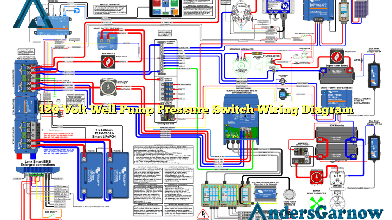
Hello and welcome to our comprehensive guide on the 120 volt well pump pressure switch wiring diagram. In this article, we will provide you with detailed information and step-by-step instructions to help you understand and successfully install your pressure switch. Whether you are a professional electrician or a DIY enthusiast, this guide will assist you in achieving optimal functionality and safety for your well pump system.
1. Understanding the Basics
Before we dive into the wiring diagram, it is essential to grasp the fundamentals of a 120 volt well pump pressure switch. This device is responsible for controlling the water pressure in your well system, ensuring it operates within safe parameters. The pressure switch activates and deactivates the pump motor based on the desired pressure settings.
When the water pressure drops below the preset low-pressure threshold, the switch activates the pump motor, allowing it to draw water from the well. Once the pressure reaches the predetermined high-pressure threshold, the switch deactivates the motor, preventing over-pressurization and potential damage to the system.
2. Components of a 120 Volt Well Pump Pressure Switch
Before proceeding with the installation, it is crucial to familiarize yourself with the components of a typical 120 volt well pump pressure switch. These components include:
| Component | Description |
|---|---|
| Power terminals | Connects the pressure switch to the power supply. |
| Pressure terminals | Connects the pressure switch to the well water system. |
| Pressure adjustment screws | Allows you to set the desired low and high-pressure thresholds. |
| Indicator lights | Displays the status of the pressure switch. |
| Switch mechanism | Controls the activation and deactivation of the pump motor. |
Understanding these components will help you navigate the wiring process more efficiently.
3. Step-by-Step Wiring Instructions
Now that you are familiar with the basics and components of a 120 volt well pump pressure switch, let’s proceed with the wiring instructions. Follow these steps carefully:
- Ensure that the power to the well pump system is switched off.
- Identify the power terminals on your pressure switch. These are usually labeled as L1 and L2.
- Connect the power supply wires to the corresponding power terminals. The black wire should be connected to L1, and the white wire (neutral) to L2.
- Locate the pressure terminals on the switch. These are commonly labeled as P1 and P2.
- Connect the well water system wires to the pressure terminals. The wire from the well pump goes to P1, and the wire from the pressure tank goes to P2.
- Now, adjust the pressure settings using the adjustment screws. Consult your well system’s specifications or manufacturer’s guidelines for the recommended pressure thresholds.
- Double-check all the connections to ensure they are secure and properly insulated.
Once you have completed these steps, you can proceed to turn on the power and test the functionality of your well pump pressure switch.
4. Advantages of a 120 Volt Well Pump Pressure Switch
The 120 volt well pump pressure switch offers several advantages:
- Cost-effective solution for controlling well water pressure.
- Reliable and durable, ensuring long-lasting performance.
- Allows for customization of pressure thresholds to suit your specific needs.
- Easy installation process, making it accessible for both professionals and DIY enthusiasts.
5. Limitations of a 120 Volt Well Pump Pressure Switch
Despite its advantages, the 120 volt well pump pressure switch does have some limitations:
- Restricted to controlling the water pressure within a specific voltage range.
- May not be suitable for high-capacity well pump systems.
- Requires periodic maintenance to ensure optimal performance.
6. Alternative Wiring Options
If a 120 volt well pump pressure switch does not suit your specific requirements, there are alternative wiring options available. These include:
- 240 volt well pump pressure switch wiring diagram: Suitable for higher voltage well pump systems.
- Wireless pressure switch: Provides wireless control and eliminates the need for physical wiring.
- Variable frequency drive (VFD) installation: Offers precise control over water pressure and pump motor speed.
Consider consulting a professional electrician to determine the best alternative wiring option for your well pump system.
7. Frequently Asked Questions (FAQ)
Q: Can I install a 120 volt well pump pressure switch myself?
A: Yes, if you have a basic understanding of electrical wiring and follow the proper safety precautions. However, it is recommended to consult a professional electrician for accurate installation and to ensure compliance with local electrical codes.
Q: How often should I check and adjust the pressure settings?
A: It is advisable to check and adjust the pressure settings at least once a year or as recommended by the well pump manufacturer. Factors such as seasonal changes and fluctuations in water demand may require periodic adjustments.
Q: Can I use a pressure switch with a different voltage rating?
A: No, it is essential to use a pressure switch with a voltage rating that matches your well pump system. Using a pressure switch with a different voltage rating can lead to system malfunctions or even pose a safety hazard.
Conclusion
In conclusion, understanding the wiring diagram for a 120 volt well pump pressure switch is crucial for ensuring the proper installation and functionality of your well pump system. By following the step-by-step instructions and considering the advantages and limitations, you can make an informed decision about the suitability of this pressure switch for your specific needs. Remember to consult a professional if you are unsure or require assistance during the installation process. With the right knowledge and careful execution, you can enjoy a reliable and efficient well pump system.

